Category: Technology & Guides

  • Thermal Scope vs Digital Night Vision: Which Works Better for Hunting at Night?

    Thermal Scope vs Digital Night Vision: Which Works Better for Hunting at Night?

    Thermal vs digital night vision is not a simple question of which technology is “better”; each system forms an image differently and has different strengths and limits at night.

    A thermal scope forms an image from differences in thermal infrared radiation reaching its detector. Digital night vision uses a light-sensitive electronic sensor to capture reflected visible or near-infrared light and convert that information into a digital image.

    That difference changes what each technology does well.

    Thermal imaging is often effective when the first task is finding a thermally distinct object in darkness. Digital night vision can provide a more visually familiar representation of terrain, vegetation, structures, and surface detail when enough ambient or infrared illumination is available.

    The useful question is therefore not:

    Which technology is always better?

    It is:

    Which type of information matters most for the task and conditions?

    For a deeper explanation of what thermal imaging reveals differently from normal vision, see what thermal imaging can reveal beyond the human eye.

    Thermal Imaging and Digital Night Vision Use Different Signals

    The most important difference starts before image processing begins.

    Thermal Imaging

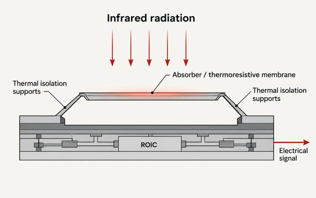
    Thermal imaging detects thermal infrared radiation reaching the sensor.

    Objects and surfaces produce different infrared signals according to factors including temperature, emissivity, material, and environmental conditions. The detector converts those differences into image data that can be processed and shown on a display.

    Visible illumination is therefore not required for the basic thermal image-forming process.

    Digital Night Vision

    Digital night vision works more like a highly sensitive digital imaging system.

    An objective lens directs reflected visible or near-infrared light onto an electronic image sensor. That signal is processed and presented on an internal display.

    Available illumination may come from:

    • moonlight;
    • starlight;
    • artificial visible light;
    • near-infrared illumination.

    When natural or ambient illumination is insufficient, many digital night-vision systems can use active IR illumination to provide additional reflected light for the image sensor.

    This is fundamentally different from thermal imaging, which does not require active illumination to reveal thermal contrast.
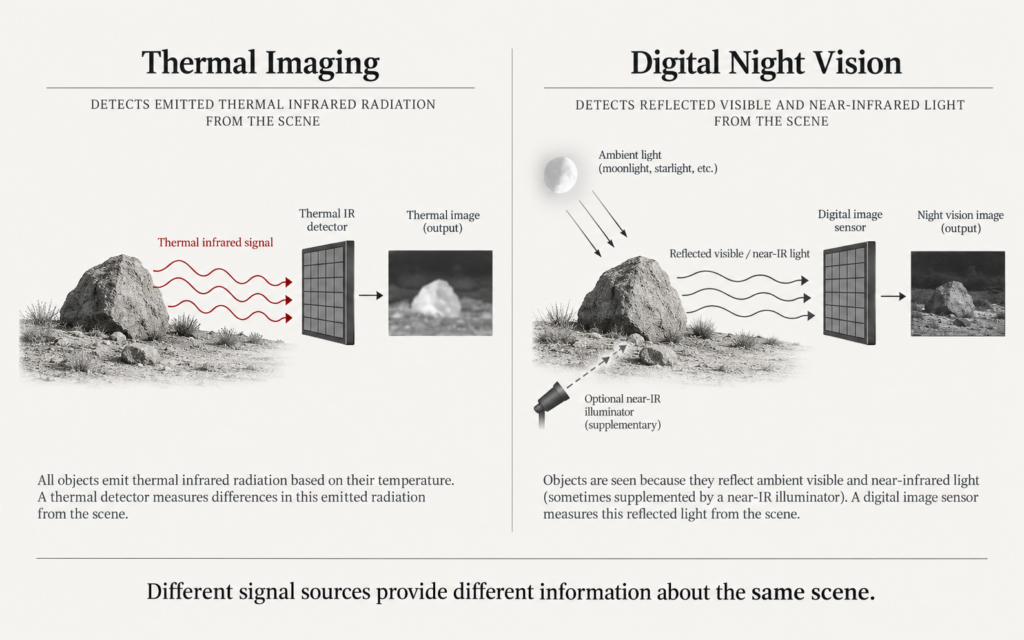
    Diagram comparing thermal infrared imaging with reflected-light digital night vision

    What Happens in Complete Darkness?

    Complete darkness highlights one of the clearest differences between the two technologies.

    Thermal imaging can continue forming an image because visible illumination is not its required signal.

    If a subject produces enough thermal contrast relative to the background, it can remain detectable even where the human eye sees almost nothing.

    Digital night vision has a different requirement.

    If there is not enough ambient visible or near-infrared light reaching the image sensor, active IR illumination may be needed.

    This does not make digital night vision inferior.

    It means the two systems solve darkness in different ways:

    thermal imaging detects thermal infrared differences already present in the scene;

    while:

    digital night vision needs reflected light reaching its sensor.

    Thermal Imaging Often Makes Detection Easier

    Imagine scanning a dark field or tree line.

    The visible scene may contain dark vegetation, dark soil, shadowed terrain, and objects with similar colors or textures.

    A digital night-vision image can preserve much of that visible scene structure.

    That can be useful, but it also means a subject remains embedded within the visual background.

    Thermal imaging approaches the same scene differently.

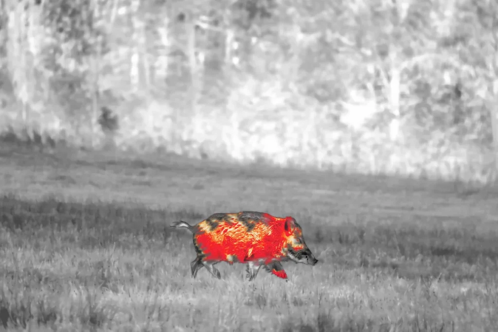
    If the subject produces a sufficiently different infrared signal from its surroundings, it may stand out clearly even when visible contrast is weak.

    This is why thermal imaging can be particularly effective for detection.

    But detection is only the first information task.

    Detection Is Not Identification

    A visible thermal signature does not automatically contain enough spatial information to determine exactly what produced it.

    At distance, a thermal image may show:

    • a warm region;
    • movement;
    • approximate size;
    • a partial silhouette.

    That may be sufficient for detection.

    It may not be sufficient for recognition or identification.

    Recognition requires more usable information about the object’s general form.

    Identification requires more information again, depending on what distinction must be made.

    The same caution applies to digital night vision.

    A bright or visually detailed image is not automatically sufficient for reliable identification if the subject is too small, blurred, overexposed, partially obscured, or outside the useful range of the optical system.

    For the full distinction, see our guide to thermal detection, recognition, and identification.

    Digital Night Vision Often Provides More Familiar Scene Detail

    Digital night vision has an important advantage that should not be understated:

    its image can resemble a conventional visual scene more closely.

    Depending on illumination, optics, sensor performance, focus, and processing, digital night vision may preserve recognizable detail in:

    • ground texture;
    • branches;
    • fences;
    • paths;
    • surface markings;
    • object edges;
    • surrounding terrain.

    This can make navigation and scene interpretation more intuitive.

    Thermal imaging often suppresses much of that visible texture because it is representing infrared contrast rather than visible reflectance.

    A surface that appears visually detailed may look thermally uniform.

    Conversely, two surfaces that look nearly identical to the eye may appear very different thermally.

    Neither representation is universally more informative.

    They reveal different information.

    Thermal Contrast and Visual Contrast Are Different

    Digital night vision depends heavily on reflected-light contrast.

    If a dark object sits against a similarly dark background, visual separation can remain difficult even when the image is bright enough to view.

    Thermal imaging depends instead on differences in infrared radiation reaching the detector.

    A visually camouflaged object can therefore remain thermally distinct if enough thermal contrast exists.

    But the reverse can also occur.

    If a target and its background approach similar apparent temperatures, thermal contrast can decrease even though the object might remain easy to distinguish visually when sufficient light is available.

    This is why thermal imaging should not be described as automatically superior in every night scene.

    What Happens When Digital Night Vision Uses IR Illumination?

    Active near-infrared illumination can provide additional light that a digital image sensor can detect even though the human eye may see little or none of it.

    This can substantially improve a digital night-vision image when ambient illumination is weak.

    But active illumination introduces its own considerations.

    Nearby:

    • grass;
    • branches;
    • precipitation;
    • dust;
    • reflective surfaces

    can return infrared illumination toward the imaging system and create foreground brightness or backscatter.

    The practical result depends on:

    • illuminator output;
    • beam pattern;
    • distance;
    • weather;
    • sensor sensitivity;
    • exposure control;
    • scene geometry.

    IR illumination should therefore be treated as part of the imaging system rather than as an unlimited substitute for natural light.

    Does Thermal Imaging Have a Glare Advantage?

    Visible-light and digital night-vision systems can be affected by strong visible light sources and reflections because their image is built from reflected light.

    Thermal imaging is not affected by visible-light glare in the same way.

    A visible spotlight, for example, does not become the fundamental image-forming signal for a thermal detector.

    That does not mean a thermal image is immune to every high-contrast condition.

    A very warm object, a large thermal contrast, reflective low-emissivity surfaces, or automatic gain-control behavior can still dominate the displayed image.

    The accurate conclusion is:

    thermal imaging is less dependent on visible-light conditions, not immune to all high-contrast scenes.

    Which Technology Works Better Around Vegetation?

    Neither technology sees directly through solid vegetation.

    Leaves, branches, trunks, and dense physical cover can block information.

    Thermal imaging may make exposed parts of a thermally distinct subject easier to locate through gaps in sparse vegetation.

    Digital night vision may provide clearer visible detail of:

    • leaves;
    • branches;
    • openings;
    • ground structure;
    • surrounding terrain.

    This creates an important distinction:

    thermal imaging can help locate thermal contrast;

    while:

    digital night vision can provide more familiar structural information about the visible scene.

    Dense physical cover remains dense physical cover for both.

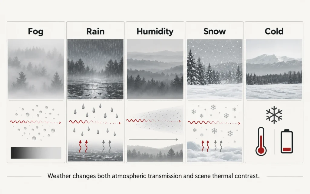
    Fog, Rain, and Humidity Affect Both Systems

    No technically accurate comparison should describe either technology as unaffected by weather.

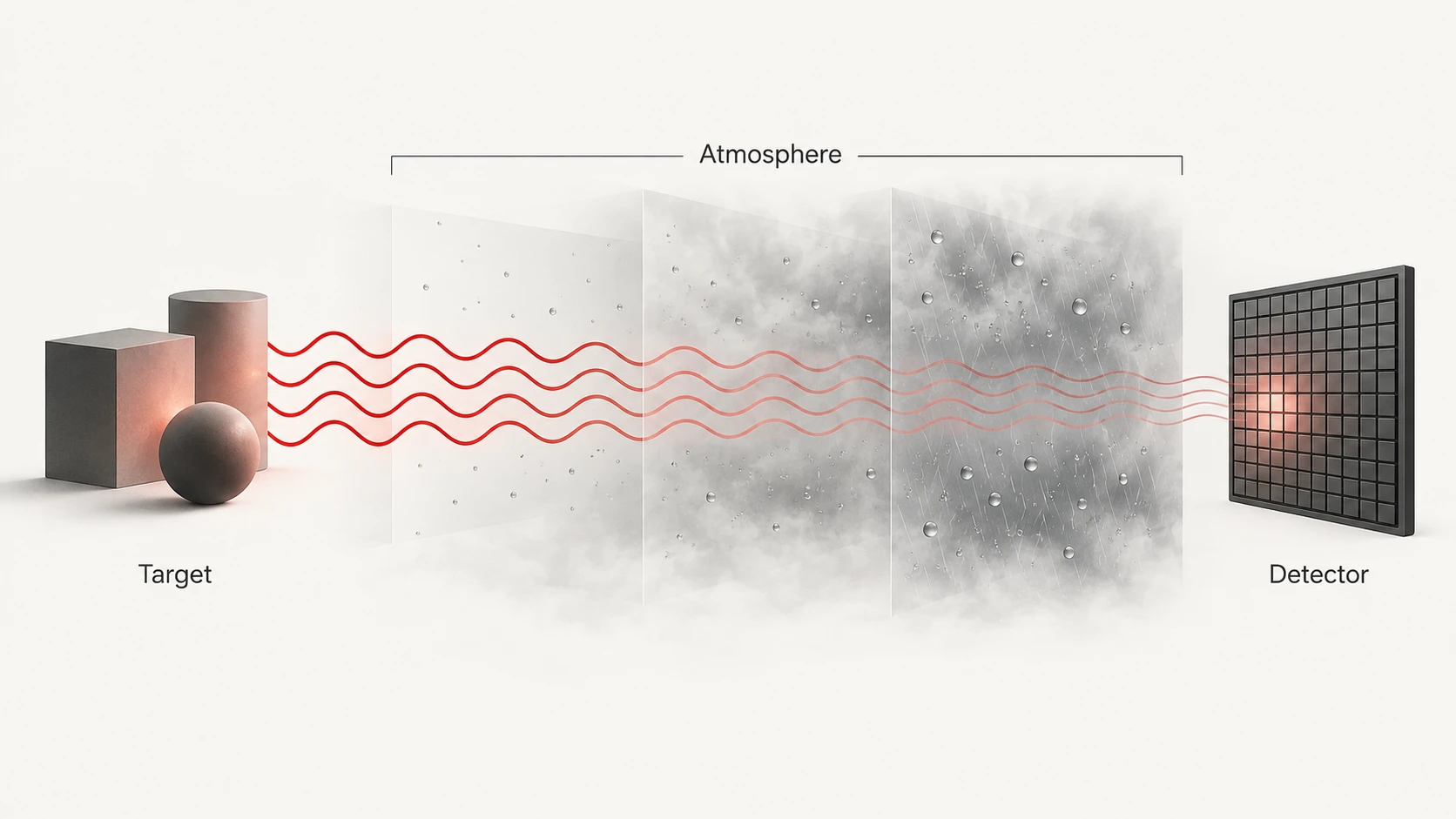
    Thermal infrared radiation can be attenuated by:

    • fog;
    • rain;
    • humidity;
    • atmospheric path length.

    Digital night vision can also lose contrast in poor visibility.

    When active IR illumination is used, moisture or particles in the air can also return illumination toward the sensor and increase backscatter.

    Which image remains more useful depends on:

    • weather severity;
    • distance;
    • target contrast;
    • available illumination;
    • wavelength;
    • optics;
    • sensor sensitivity;
    • processing.

    Thermal imaging can outperform visible imaging in some low-visibility conditions, but it should not be described as literally seeing through dense fog.

    For the full environmental explanation, see how weather affects thermal imaging.

    Resolution Numbers Cannot Be Compared Directly Across the Two Technologies

    It is tempting to compare:

    thermal detector resolution

    with:

    digital CMOS sensor resolution

    and assume that the larger number identifies the better system.

    That comparison is incomplete.

    The sensors are collecting different types of information.

    A digital night-vision sensor may contain millions of pixels but still have limited useful information when scene illumination is weak.

    A thermal detector may have fewer native samples but provide strong target-to-background separation when thermal contrast is high.

    Image quality depends on the complete system:

    • sensor;
    • optics;
    • field of view;
    • sensitivity;
    • illumination;
    • focus;
    • processing;
    • display.

    Pixel count alone does not determine which technology is more useful.

    NETD Matters to Thermal Imaging, Not Digital Night Vision in the Same Way

    NETD is a thermal-imaging sensitivity metric.

    It describes how small a thermal difference can be distinguished relative to system noise under specified measurement conditions.

    Digital night vision uses different performance characteristics because its sensor responds primarily to reflected visible or near-infrared light rather than thermal infrared radiation.

    This means a specification such as:

    18 mK

    cannot be directly compared with the resolution or low-light specification of a CMOS digital-night-vision sensor.

    They describe different properties.

    For more detail, see NETD in thermal imaging.

    Field of View Matters for Both

    Field of view determines how much of the scene is visible at one time.

    A wider field of view can make scanning and navigation easier.

    A narrower field of view can make a distant object occupy more of the sensor image.

    This trade-off applies to both thermal and digital systems.

    The useful comparison therefore includes:

    • focal length;
    • sensor dimensions;
    • base magnification;
    • field of view;
    • intended distance.

    Field of view should not be evaluated in isolation.

    Digital Zoom Does Not Add Native Information to Either System

    The same rule applies to thermal imaging and digital night vision:

    digital zoom enlarges information already captured by the sensor.

    It does not add new physical detector samples.

    A higher-resolution digital sensor may provide more room for enlargement before degradation becomes obvious.

    Similarly, a higher-resolution thermal detector may preserve more spatial information when enlarged.

    But:

    maximum digital zoom is not the same as native image detail.

    Image processing and super-resolution can change presentation, but they should be evaluated separately from native sensor information.

    Which Is Better for Scanning?

    When the primary task is:

    quickly finding a thermally distinct subject somewhere within a dark scene,

    thermal imaging often has an advantage.

    A target may stand apart from visual background clutter because the system is not relying on visible color or reflected-light contrast.

    That does not mean every thermal signal represents the subject being searched for.

    Rocks, structures, machinery, recently heated surfaces, and other objects can also produce strong thermal signatures.

    Detection should therefore be followed by interpretation and confirmation.

    Which Is Better for Understanding the Scene?

    When the main task is:

    interpreting terrain and visually familiar scene structure,

    digital night vision can have a strong advantage.

    With sufficient ambient or active illumination, the image may preserve:

    • paths;
    • vegetation structure;
    • fences;
    • surface patterns;
    • object markings;
    • spatial context.

    This can make the scene easier to relate to normal daytime visual experience.

    The trade-off is that the same visual detail can also increase background clutter.

    Which Is Better at Long Range?

    There is no technically defensible answer based on the technology name alone.

    Useful range depends on the complete configuration.

    For thermal imaging, important factors include:

    • target size;
    • target-to-background thermal contrast;
    • detector resolution;
    • NETD;
    • focal length;
    • field of view;
    • atmospheric transmission.

    For digital night vision, important factors include:

    • target size;
    • available illumination;
    • image-sensor sensitivity;
    • optical aperture;
    • focal length;
    • field of view;
    • IR illumination where used;
    • atmospheric conditions.

    Manufacturers’ quoted range figures should therefore be compared only when the underlying task is clear.

    A thermal detection range should not be directly compared with a digital-night-vision observation distance or illuminator range as though they describe the same thing.

    Thermal vs Digital Night Vision: Practical Comparison

    QuestionThermal ImagingDigital Night Vision
    Primary scene informationThermal infrared differencesReflected visible / near-IR light
    Visible light requiredNoUses ambient or active illumination
    Complete darknessPassive operation possibleMay require IR illumination
    Finding thermal contrastOften strongDepends on visual contrast
    Familiar terrain detailUsually less naturalOften stronger
    Visible camouflageMay matter less if thermal contrast existsCan remain visually relevant
    Dense physical obstructionCannot see throughCannot see through
    Fog / rainCan degradeCan also degrade
    Active illuminationNot required for thermal image formationOften useful in very low light
    Digital zoomDoes not add native detailDoes not add native detail
    Useful rangeSystem- and scene-dependentSystem-, illumination-, and scene-dependent

    The purpose of this table is not to name one winner.

    It shows why the two technologies solve different parts of the night-observation problem.

    When Thermal Imaging Is Usually the Better Fit

    Thermal imaging may be the stronger choice when the priority is:

    • scanning a wide dark area for thermal signatures;
    • operating without active illumination;
    • detecting objects that visually blend into the background;
    • working across changing visible-light conditions;
    • prioritizing detection over familiar visible-scene appearance.

    The exact result still depends on detector resolution, NETD, optics, field of view, focus, processing, and the scene itself.

    When Digital Night Vision Is Usually the Better Fit

    Digital night vision may be the stronger choice when the priority is:

    • seeing terrain in a visually familiar way;
    • interpreting branches, fences, paths, and surface detail;
    • working where ambient or active illumination is sufficient;
    • using visual scene information as part of recognition;
    • using a digital day/night platform designed to cover both illuminated and low-light conditions.

    Again, the exact result depends on the product and environment.

    A Current Yubeen Example of Digital Day & Night Vision

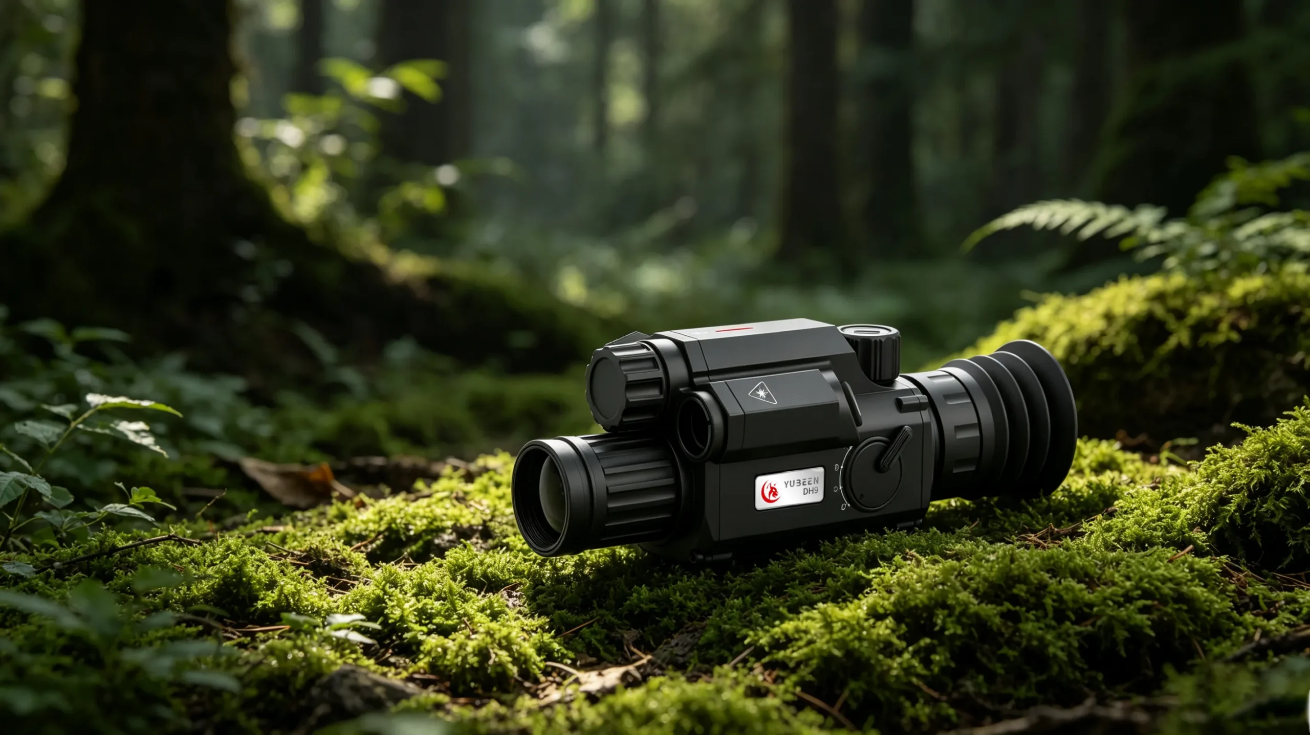
    The YUBEEN DH9 represents Yubeen’s current digital day & night vision platform.

    Its imaging architecture uses a CMOS sensor and digital image-processing chain rather than a thermal detector.

    That distinction matters more than simply comparing sensor pixel counts.

    Digital night vision and thermal imaging are collecting different information from the scene, so their sensor-resolution numbers should not be treated as directly equivalent measures of performance.
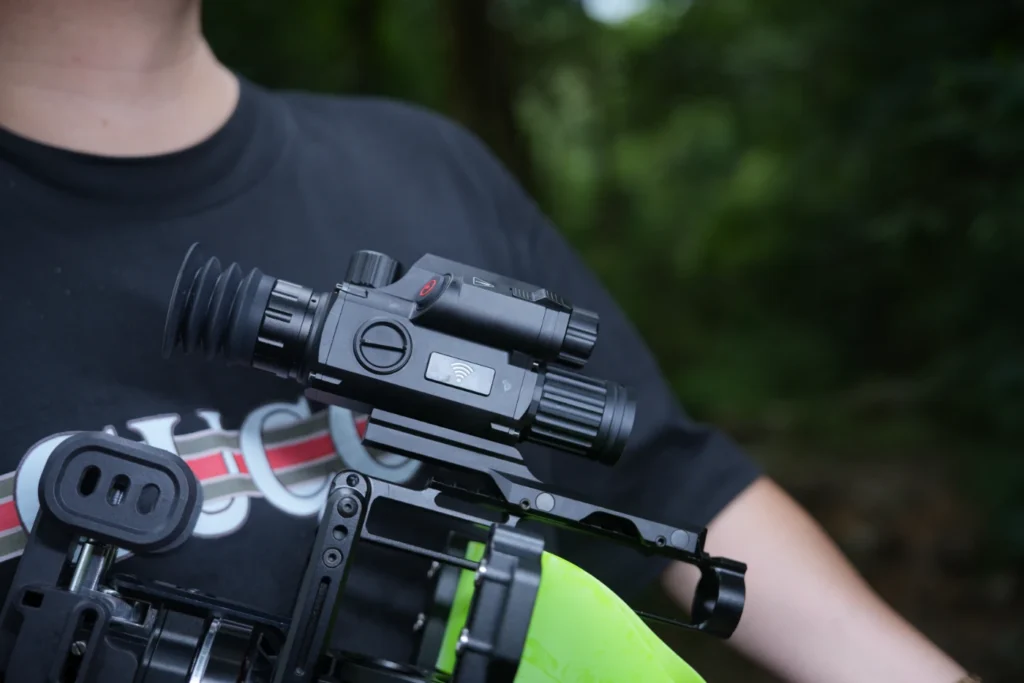
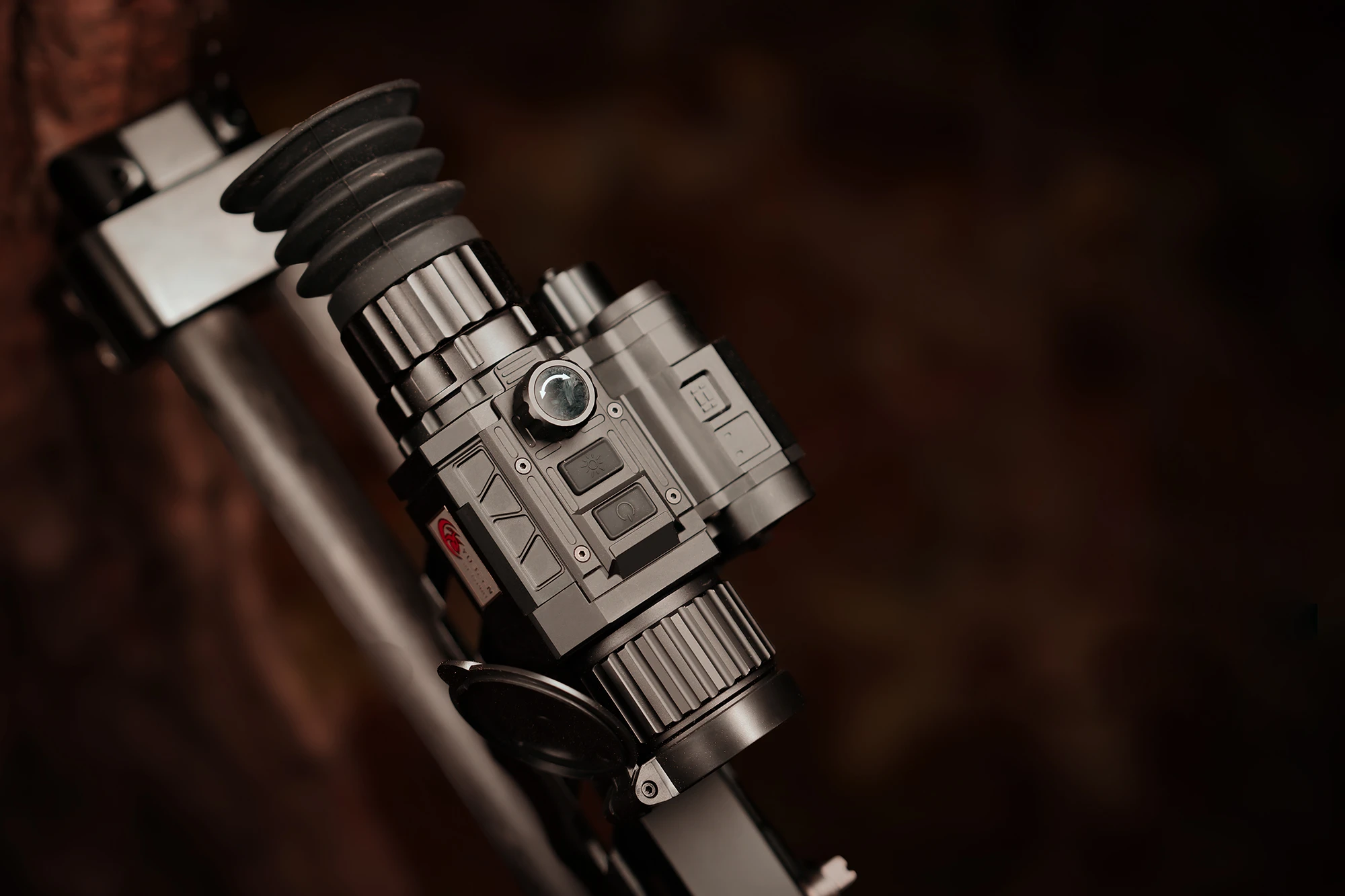
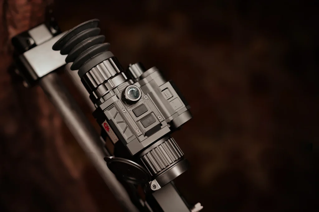
    Yubeen DH9 digital day and night vision riflescope

    For the complete current specification set, see the YUBEEN DH9 product page.

    Yubeen Thermal Products Represent a Different Imaging Approach

    Yubeen’s current thermal imaging products use thermal detector architecture rather than the visible / near-infrared CMOS imaging chain used by digital day & night vision.

    Their practical performance depends on the complete system, including:

    • detector resolution;
    • NETD;
    • lens;
    • field of view;
    • focus;
    • image processing;
    • target-to-background thermal contrast;
    • environmental conditions.

    These specifications should always be checked from the documentation for the exact current model rather than transferred from an older product or another product in the range.

    For that reason, this article does not use one thermal product’s specification sheet as a universal benchmark against the DH9.

    The purpose is to compare the technologies—not force unlike specifications into a numerical ranking.
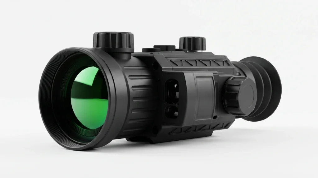
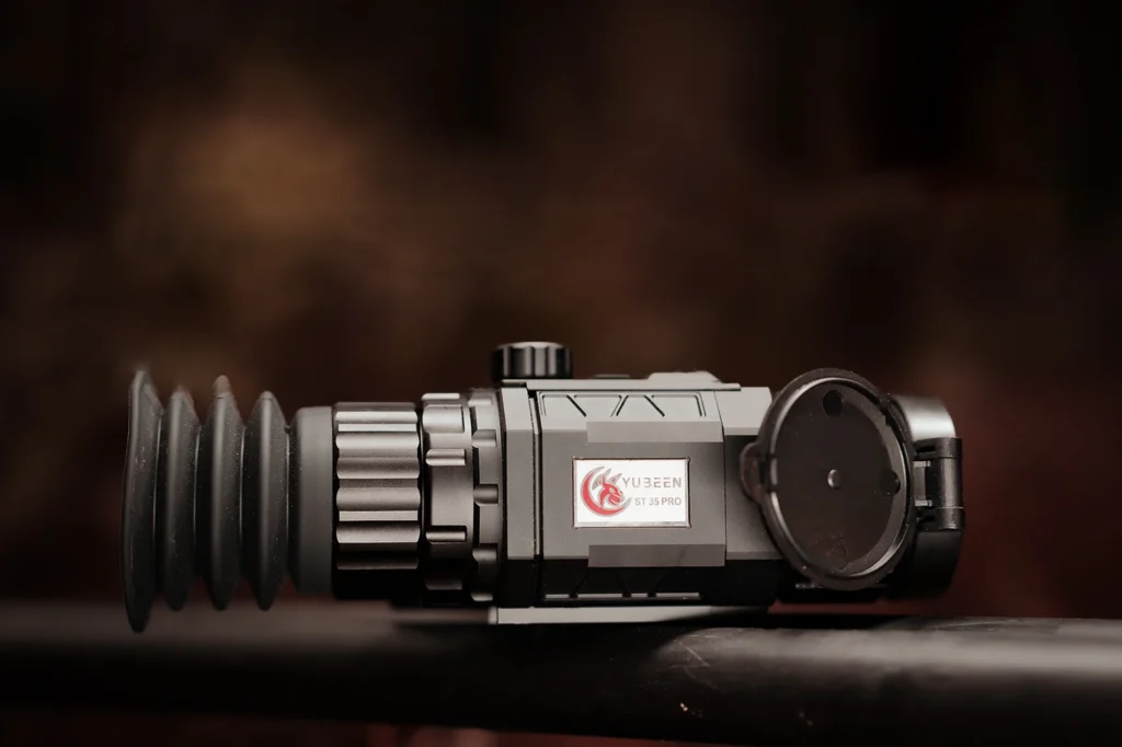
    Yubeen GX55L thermal imaging riflescope for field use
    A current Yubeen thermal imaging product. Exact specifications vary by model.

    You can review the current Yubeen thermal imaging range after deciding which type of scene information is most important for the intended use.

    Could the Two Technologies Complement Each Other?

    Yes.

    Thermal imaging and digital night vision can provide different information about the same environment.

    Conceptually:

    thermal imaging is often strong for locating thermal contrast;

    while:

    digital night vision is often strong for visually familiar scene detail when sufficient light is available.

    That does not mean every user needs both.

    Cost, weight, workflow, mounting, local regulations, observation distance, and the actual task all influence whether one technology or a combination makes sense.

    Applicable hunting and equipment regulations should always be checked for the location where the equipment will be used.

    How to Choose Between Them

    Use the following questions:

    1. Is the first priority finding a thermally distinct subject or understanding terrain?
    2. Will useful ambient light normally be available?
    3. Is active IR illumination practical for the intended environment?
    4. How important is passive operation in complete darkness?
    5. What target size and distance are realistic?
    6. Is wide-area scanning or a narrower distant view more important?
    7. How important is familiar visual detail for recognition?
    8. What weather conditions are likely?
    9. What weight, runtime, controls, and mounting arrangement are acceptable?
    10. What does local regulation permit?

    Then compare the exact products rather than selecting solely by technology category.

    There Is No Universal Winner

    Thermal imaging and digital night vision do not compete by producing the same information in two different ways.

    They begin with different information.

    Thermal imaging emphasizes infrared contrast and does not require visible illumination.

    Digital night vision uses reflected light and can provide a more familiar representation of the scene when sufficient ambient or active illumination is available.

    For fast detection in complete darkness, thermal imaging often has a strong advantage.

    For interpreting visually familiar terrain and surface detail, digital night vision can be more useful.

    The better choice is therefore determined by the task, scene, and product—not by a universal ranking.

    FAQ

    Is Thermal Always Better Than Digital Night Vision?

    No. Thermal imaging can be especially effective for detecting thermal contrast without visible illumination, while digital night vision can provide more familiar terrain and surface detail when sufficient light is available.

    Can Digital Night Vision Work in Complete Darkness?

    It can when the system uses suitable active infrared illumination. Without enough ambient or active illumination, a digital night-vision sensor may have insufficient reflected light to form a useful image.

    Does Thermal Imaging Need an IR Illuminator?

    No. Thermal imaging detects thermal infrared radiation from the scene and does not require active IR illumination to create its thermal image.

    Which Technology Is Better for Detecting Animals at Night?

    Thermal imaging often makes a thermally distinct animal easier to locate against a dark background, but detection is not the same as identification. Distance, thermal contrast, resolution, optics, and atmosphere still matter.

    Which Gives More Natural-Looking Detail?

    Digital night vision generally produces an image closer to a conventional visible-light scene because it is based on reflected visible or near-infrared light.

    Does Thermal See Through Brush Better Than Digital Night Vision?

    Neither sees through solid vegetation. Thermal may reveal exposed warm areas through gaps where thermal contrast exists, while digital night vision may provide more visible structural detail of the vegetation itself.

    Which Has Longer Range?

    Neither technology has a universal range advantage. Useful distance depends on the exact sensor, optics, field of view, illumination or thermal contrast, atmosphere, target size, and task.
  • Smart Ballistics in Thermal Optics: What the Software Can—and Cannot—Do

    Smart Ballistics in Thermal Optics: What the Software Can—and Cannot—Do

    Smart ballistics in thermal optics refers to software-assisted functions that can combine information from the thermal device, a laser rangefinder, internal sensors, and configured system data. Depending on the exact product, the software may present additional information inside the display to support the user’s decision-making.

    The important distinction is that ballistic software does not improve thermal detector resolution, NETD, lens quality, or native image detail. It also does not guarantee where a projectile will land. Its value depends on the accuracy of the available data, the supported software functions, the hardware integration, and correct setup of the complete system.

    What Does “Smart Ballistics” Actually Mean?

    The term can describe several different functions, so it should never be treated as one universal feature.

    Depending on the product, ballistic-related software may combine information from:

    • an integrated laser rangefinder;
    • internal orientation sensors;
    • stored equipment profiles;
    • configured system data;
    • software calculations;
    • the thermal display interface.

    The result may then be presented as additional information inside the device.

    The exact implementation differs between products.

    For this reason, buyers should ask what the software actually calculates and displays, rather than relying on the phrase “smart ballistics” alone.

    Rangefinding and Ballistic Software Are Different Functions

    An integrated laser rangefinder measures distance.

    Ballistic-related software uses information according to the implementation supported by the device.

    They are not the same feature.

    A scope can include:

    • an LRF without ballistic software;
    • ballistic-related software that requires manually supplied distance information;
    • or an integrated system where supported functions can use LRF information.

    The exact relationship must be confirmed for the individual model and software version.

    For a detailed comparison of integrated ranging itself, see LRF and non-LRF thermal scopes.

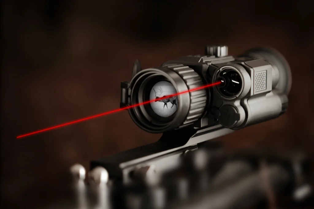
    Yubeen thermal scope with integrated laser rangefinder

    Distance Information Is Only One Part of the System

    Knowing distance can remove one source of uncertainty, but distance alone does not describe the complete external environment or mechanical system.

    A ballistic-related feature may depend on several categories of information supported by the device.

    If those inputs are incomplete, outdated, incorrect, or unsupported, the calculated output can also be unreliable.

    This is why smart ballistic functions should be treated as decision-support software, not as an automatic guarantee of accuracy.

    The software cannot independently verify every physical variable affecting the complete system.

    Smart Ballistics Does Not Replace Correct Zero Verification

    Ballistic-related software works on top of the existing optical and mechanical setup.

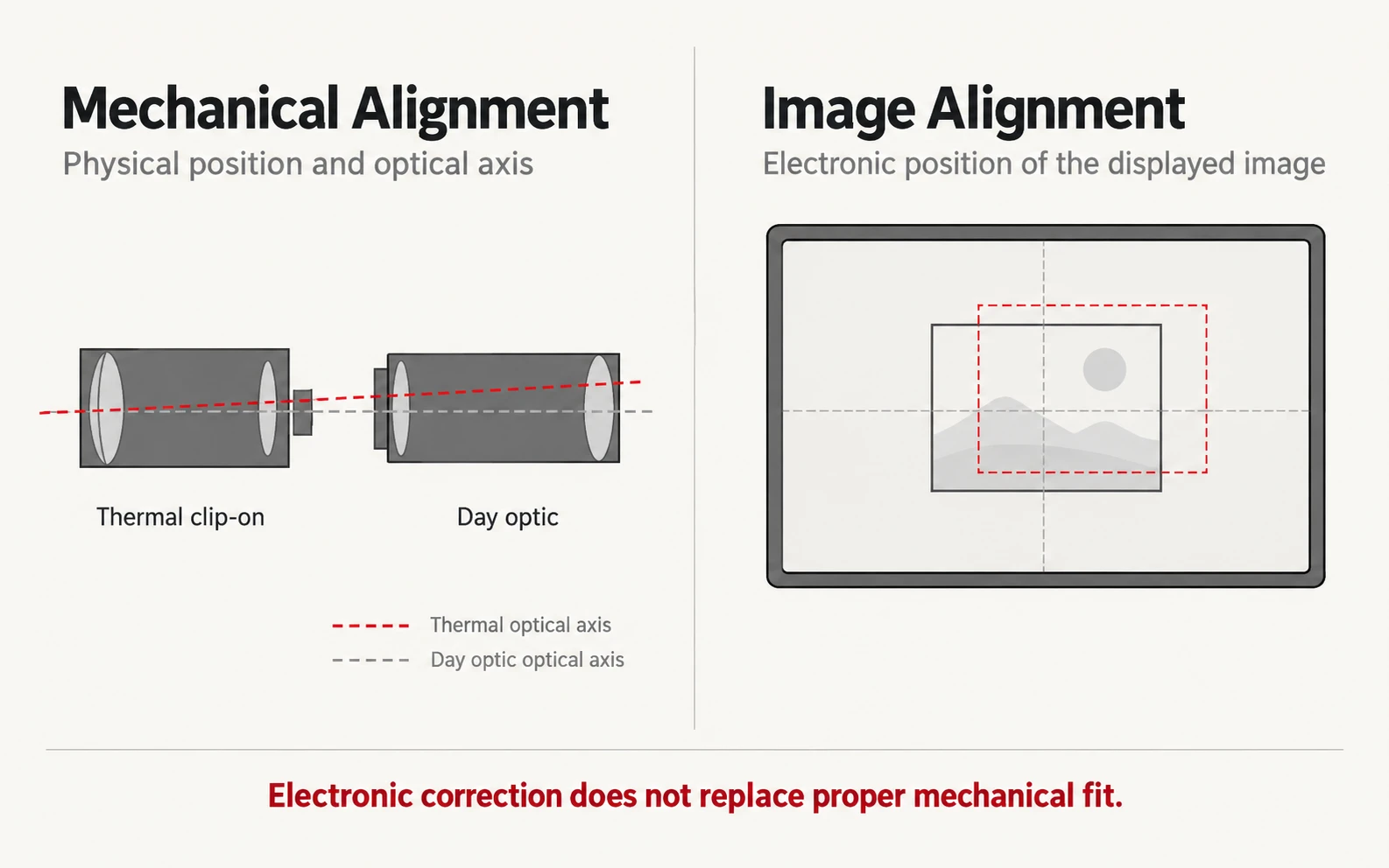
    If the underlying system is not correctly installed or verified, software cannot repair the physical problem.

    The same applies when:

    • the optic or mount has shifted;
    • the wrong profile is active;
    • the product configuration has changed;
    • the software version does not match the expected function;
    • stored data is no longer applicable.

    Software should therefore supplement a correctly configured system rather than replace the normal verification process.

    For broader mechanical compatibility, see how to match a thermal scope with your rifle.

    Angle and Orientation Sensors Provide Additional Context

    Some electronic optics can include orientation sensors capable of detecting information such as device angle or cant.

    Where supported, software can use this information as part of its internal calculation or display logic.

    The important point is that:

    sensing an angle and correctly applying that information are two separate functions.

    A buyer should therefore confirm:

    • which sensors are present;
    • which software functions use them;
    • whether their information is displayed directly;
    • whether they affect any ballistic-related calculation;
    • which software or firmware version enables the function.

    Generic marketing language such as “real-time elevation compensation” is not enough to establish what the product actually does.

    Ballistic Software Does Not Improve Thermal Image Quality

    A ballistic calculator and a thermal imaging system solve different problems.

    Thermal image quality depends on factors such as:

    • detector resolution;
    • pixel pitch;
    • NETD;
    • lens focal length;
    • aperture;
    • focus;
    • image processing;
    • refresh rate;
    • display quality.

    Ballistic-related software does not increase any of these physical imaging specifications.

    A device can therefore have sophisticated software but only moderate imaging performance, or strong imaging performance with minimal ballistic functions.

    The two areas should be evaluated independently.

    For a broader system-level comparison, see what defines a high-end thermal scope.

    Magnification Does Not Make Ballistic Information More Accurate

    Thermal magnification changes how large the image appears.

    It does not make the underlying distance measurement or software calculation inherently more accurate.

    Digital zoom also does not create additional native thermal information.

    This distinction matters because several functions can appear on the same display while still operating independently:

    • thermal imaging;
    • magnification;
    • rangefinding;
    • orientation sensing;
    • ballistic-related software.

    A sophisticated interface should integrate these functions clearly without encouraging the user to confuse one with another.

    For the imaging side of the issue, see our thermal scope magnification guide.

    Picture-in-Picture Is a Display Feature, Not a Ballistic Function

    Picture-in-picture, or PIP, can show an enlarged section of the thermal image while maintaining a wider scene in the main display.

    This can help preserve environmental awareness while inspecting a smaller area in greater apparent detail.

    PIP itself does not:

    • measure distance;
    • calculate a trajectory;
    • increase detector resolution;
    • verify zero;
    • improve NETD.

    It is a display function.

    If ballistic-related information is shown at the same time as PIP, the two features remain technically separate.

    Display Features Should Present Information Clearly

    Adding more electronic functions is useful only if the user can understand the interface quickly.

    A well-designed system should make it clear which information comes from:

    • the thermal detector;
    • the LRF;
    • the orientation sensors;
    • stored settings;
    • software calculations.

    Important interface considerations include:

    • readable text;
    • clear units;
    • logical menu organization;
    • understandable status indicators;
    • easy access to frequently used functions;
    • minimal obstruction of the thermal image.

    A feature-rich system is not automatically a better system if important information is difficult to interpret.

    Software Version Matters

    Ballistic and other smart functions depend heavily on software.

    Two devices with similar hardware can behave differently if their software or firmware versions differ.

    Before comparing products or documenting features, confirm:

    • the exact model;
    • hardware revision where relevant;
    • current firmware;
    • current app version where applicable;
    • supported functions;
    • supported profiles;
    • whether features differ by market or product version.

    This is particularly important for articles, catalogues, and distributor materials.

    A function that existed in a demonstration firmware version should not automatically be presented as a current production feature.

    AI Image Processing and Smart Ballistics Are Not the Same Thing

    The term “AI” can also create confusion.

    Image-processing algorithms may be used to improve the visual presentation of thermal data through functions such as:

    • noise reduction;
    • edge enhancement;
    • contrast processing;
    • interpolation;
    • super-resolution methods.

    These functions affect image presentation.

    Ballistic-related software processes a different category of information.

    Even if both systems use advanced algorithms, they should not be combined into one claim such as:

    “AI automatically improves image quality and guarantees ballistic accuracy.”

    That would describe two independent systems as if they were one.

    The imaging system and ballistic system should be evaluated separately.

    What Smart Ballistics Cannot Guarantee

    Ballistic-related software should not be described as guaranteeing a result.

    It cannot independently guarantee:

    • correct mechanical installation;
    • correct zero;
    • correct stored information;
    • stable mounting;
    • accurate environmental assumptions;
    • consistent equipment behavior;
    • reliable range measurement under every condition;
    • responsible user judgment.

    Software output should therefore be understood as calculated information based on the data and functions available to the system.

    That is fundamentally different from a guaranteed physical outcome.

    Reliability Matters More as Software Complexity Increases

    More integrated functions create more dependencies.

    An LRF-equipped device with software integration may depend on:

    • detector operation;
    • rangefinder operation;
    • internal sensors;
    • stored configuration;
    • battery condition;
    • processing hardware;
    • firmware;
    • display behavior.

    This does not mean complex products are inherently unreliable.

    It means reliability testing should consider the complete system rather than only one specification.

    Power management is also relevant because LRF, recording, wireless connectivity, processing, and display functions all consume energy.

    For a broader troubleshooting framework, see thermal scope reliability.

    Use a Feature-Verification Checklist Before Comparing Products

    For smart ballistic functions, verify the implementation rather than the marketing label.

    FactorWhat to Confirm
    LRFIs it integrated into the exact model?
    LRF outputHow and where is distance displayed?
    Ballistic functionDoes the exact product actually include it?
    Data sourceWhat information does the system use?
    Orientation sensorsAre angle/cant sensors present and supported?
    ProfilesCan the exact model store profiles?
    DisplayHow is calculated information shown?
    PIPIs it supported independently of ballistic functions?
    SoftwareWhich firmware enables the feature?
    AppIs an external app required?
    ConnectivityDoes the feature depend on Wi-Fi/Bluetooth?
    StorageAre settings stored locally?
    PowerDoes the function affect runtime?
    DocumentationIs the function described in current manuals?
    SupportCan the manufacturer confirm the exact implementation?

    If these questions cannot be answered, the phrase “smart ballistics” is not specific enough for a reliable product comparison.

    How to Evaluate Ballistic-Related Functions on Current Yubeen Products

    Do not assume that every Yubeen thermal scope has ballistic-related software.

    Feature availability should be confirmed for the exact current product.

    Use this sequence:

    1. identify the exact model and hardware version;
    2. confirm whether an LRF is integrated;
    3. confirm whether ballistic-related software is supported;
    4. confirm whether orientation sensors are used;
    5. verify what information the system accepts;
    6. verify what information the system outputs;
    7. check how the result is displayed;
    8. verify whether profiles are supported;
    9. confirm the current firmware version;
    10. check whether an app or wireless connection is required;
    11. confirm current documentation;
    12. confirm current support and warranty terms.

    Link Yubeen thermal imaging scopes to the current thermal product category.

    Do not publish unverified claims such as:

    • “automatic aiming”;
    • “guaranteed accuracy”;
    • “always correct point of impact”;
    • “works at every magnification”;
    • “fully compensates for all environmental conditions.”

    If a current product genuinely supports a specific ballistic-related function, describe only the verified capability documented for that exact model.

    What Professional Buyers Should Ask Before Ordering

    For B2B evaluation, confirm the software function before treating it as part of the commercial specification.

    Request or verify:

    • current product specification;
    • current user manual;
    • current firmware version;
    • supported functions;
    • LRF implementation;
    • software or app requirements;
    • supported display functions;
    • current sample behavior;
    • relevant certifications;
    • warranty terms;
    • after-sales support.

    A sample evaluation is particularly valuable for software-dependent functions because a static specification sheet cannot fully demonstrate menu behavior or integration.

    Final Thoughts

    Smart ballistic functions can make electronic optics more informative by bringing ranging, sensor information, software calculations, and display functions into one interface.

    Their value comes from integration—not from replacing the underlying imaging system or removing every source of uncertainty.

    A laser rangefinder measures distance. A thermal detector creates the image. Orientation sensors provide additional context. Software processes supported information. The display presents the result.

    Those components should be evaluated individually and then as a complete system.

    The best smart feature is not the one with the strongest marketing claim. It is the one whose inputs, calculations, display behavior, software version, limitations, and product support are clearly documented.

    FAQ

    Does smart ballistic software automatically guarantee accuracy?

    No.
    Ballistic-related software provides calculated information based on the data and functions available to the system. It cannot independently guarantee mechanical setup, zero, range measurement, environmental assumptions, or physical outcome.

    Does an integrated LRF automatically mean the scope has ballistic calculation?

    No.
    An LRF provides distance information. Ballistic-related functions are separate software capabilities and must be confirmed for the exact model.

    Does smart ballistics improve thermal image quality?

    No.
    Thermal image quality depends on the detector, optics, NETD, focus, processing, refresh rate, and display. Ballistic software processes different information.

    Is picture-in-picture part of the ballistic system?

    Not necessarily.
    PIP is primarily a display function. A product may allow PIP and ballistic-related information to be used at the same time, but they remain separate functions.

    Can AI image processing and ballistic software be the same feature?

    No.
    AI or advanced image processing typically affects image presentation. Ballistic-related software processes range, sensor, and configured system information. They may coexist in one device but perform different tasks.

    What should buyers verify before comparing smart ballistic thermal scopes?

    Confirm the exact model, integrated LRF, supported ballistic functions, required data sources, orientation sensors, display behavior, software version, profile support, app requirements, documentation, warranty, and technical support.

  • 12μm Pixel Pitch in Thermal Imaging: What It Changes—and What It Doesn’t

    12μm Pixel Pitch in Thermal Imaging: What It Changes—and What It Doesn’t

    Thermal detector specifications can look deceptively simple. Resolution, NETD, refresh rate and pixel pitch are often listed side by side, which makes it easy to assume that a smaller number automatically means a better thermal image.

    Pixel pitch does not work that way.

    A 12μm pixel pitch is widely used in modern thermal detector designs, and it can provide important advantages in spatial sampling, detector size and optical-system design. But it does not, by itself, determine image quality, thermal sensitivity or detection range.

    To understand what 12μm actually changes, it helps to separate the detector geometry from the rest of the thermal imaging system.

    For a broader introduction to detector resolution, thermal sensitivity and image formation, start with our thermal imaging for beginners guide.

    What Does Pixel Pitch Mean in a Thermal Detector?

    Pixel pitch is the center-to-center distance between neighboring detector elements in a focal plane array, or FPA.

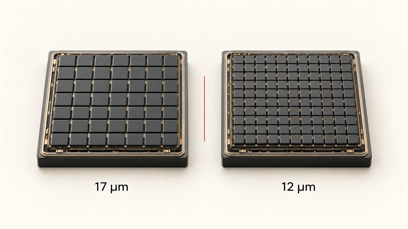
    A detector specified as having a 12μm pixel pitch places the centers of adjacent pixels 12 micrometers apart. A 17μm detector uses a 17-micrometer spacing.

    That number describes physical geometry. It does not tell you how many pixels the detector contains.

    For example, these are separate specifications:

    • Detector resolution: 384 × 288, 640 × 512 or another array format
    • Pixel pitch: 12μm, 17μm or another value

    A detector can therefore have a small pixel pitch without having a high pixel count, and a larger-pitch detector can still have a higher total resolution.

    Pixel Pitch and Detector Resolution Are Not the Same Thing

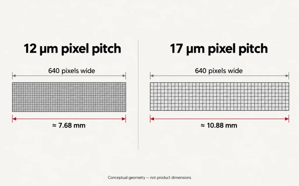
    Conceptual comparison of detector width at 12 micrometer and 17 micrometer pixel pitch

    Consider two hypothetical detectors that are both 640 pixels wide.

    With a 12μm pitch, the active width represented by those 640 pixel positions is approximately:

    640 × 12μm = 7.68 mm

    With a 17μm pitch:

    640 × 17μm = 10.88 mm

    This example does not say that one detector produces a better image. It shows that the same number of pixels can occupy a smaller physical area when the pixel pitch is reduced.

    That difference has consequences for lens design, field of view and angular sampling.

    How Pixel Pitch Affects IFOV

    One of the most useful concepts for understanding pixel pitch is Instantaneous Field of View, or IFOV.

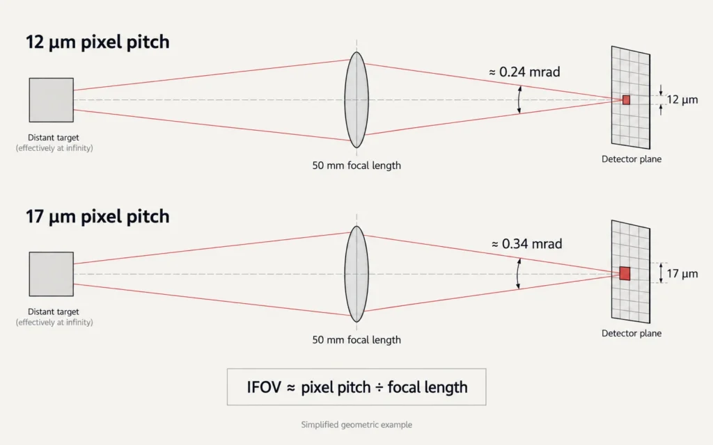
    IFOV describes the angular portion of the scene represented by an individual detector pixel. In simplified optical geometry, pixel IFOV is approximately related to:

    pixel pitch ÷ focal length

    This means that pixel pitch cannot be evaluated independently from the lens.

    For the same focal length, a smaller pixel pitch produces a smaller angular IFOV. Each pixel then covers a smaller angular portion of the scene.

    A finer IFOV can place more sampling points across a distant target and improve the amount of spatial information available for interpreting that target. But the result still depends on the complete optical and detector system.

    Same Lens, Different Pixel Pitch

    Diagram showing how pixel pitch and focal length affect thermal imaging IFOV

    As a simplified example, imagine two detectors used behind the same 50 mm focal-length lens.

    Ignoring other optical effects:

    • 12μm ÷ 50 mm ≈ 0.24 mrad
    • 17μm ÷ 50 mm ≈ 0.34 mrad

    The 12μm configuration therefore has finer theoretical angular sampling.

    However, if both detectors also have the same pixel count, the physically smaller 12μm array will normally produce a narrower field of view with that same lens.

    That may be useful for longer-distance observation, but a wider field of view may be preferable in other applications.

    There is no universally correct choice without considering the required viewing geometry.

    Why Smaller Pixels Can Support More Compact Optical Designs

    Another advantage of smaller pixel pitch appears when the goal is to maintain similar angular sampling while reducing optical size.

    Because IFOV depends on both pixel pitch and focal length, a smaller pixel pitch can achieve similar per-pixel angular sampling with a shorter focal length than a larger-pitch detector.

    Using only the pitch ratio:

    12 ÷ 17 ≈ 0.71

    In an idealized comparison, this means a 12μm detector could use roughly 71% of the focal length of a 17μm detector while maintaining similar pitch-to-focal-length angular sampling.

    That does not mean every 12μm thermal device is 29% smaller. Housing design, aperture, lens diameter, focus mechanism, detector package, electronics and other components still determine the final product dimensions.

    It does explain why smaller-pitch detectors give optical engineers more flexibility when balancing magnification, field of view and package size.

    For a closer look at the relationship between focal length, field of view and apparent target size, see our guide to thermal scope magnification.

    Does 12μm Mean Higher Thermal Resolution?

    Not automatically.

    Native thermal resolution is determined by the detector’s number of active pixels.

    For example:

    • 640 × 512 contains more detector pixels than 384 × 288
    • 384 × 288 at 12μm does not become 640 × 512 simply because its pixels are smaller
    • Pixel pitch and detector resolution should therefore always be listed separately

    Smaller pitch can allow more pixels to fit into a given physical detector area, which is one reason detector technology has moved toward smaller pixel geometries.

    But the actual resolution of a finished detector still depends on the array format selected by the manufacturer.

    Does 12μm Automatically Mean Better NETD?

    No.

    NETD, or Noise Equivalent Temperature Difference, describes a thermal imaging system’s ability to distinguish small temperature differences under specified test conditions.

    Pixel pitch is one factor in detector architecture, but NETD also depends on detector material, pixel structure, fill factor, readout electronics, integration conditions, optical f-number, calibration and signal processing.

    There is also an engineering trade-off associated with reducing pixel size.

    If square pixel geometry is compared directly, a 12μm × 12μm pixel has a geometric area of 144 square micrometers, while a 17μm × 17μm pixel has an area of 289 square micrometers.

    The smaller pixel therefore has roughly half the geometric area.

    That does not mean it must have poor thermal sensitivity. Modern detector engineering can compensate through improved materials, structures, readout circuits and image processing. Current commercial 12μm detectors can achieve very low NETD values.

    But it does mean that 12μm itself is not a thermal-sensitivity specification.

    Real commercial detector specifications demonstrate this clearly: both 12μm and 17μm detector families exist with different NETD ratings depending on the detector design.

    When comparing thermal devices, NETD should therefore be read independently from pixel pitch.

    Pixel Pitch, Field of View and Base Magnification

    Pixel pitch also influences field of view when other variables are held constant.

    If two detectors have:

    • the same resolution,
    • the same lens focal length,
    • but different pixel pitches,

    the smaller-pitch detector has a physically smaller array and therefore generally covers a narrower field of view.

    A narrower field of view makes objects occupy a larger portion of the displayed image, which can feel like greater optical or base magnification.

    This is why smaller-pitch detectors can be attractive in systems designed around longer-distance observation.

    But the trade-off matters.

    A narrow field of view can make scanning large areas more difficult, especially at shorter ranges. A wider field of view can make target acquisition and situational awareness easier.

    Neither characteristic is universally better.

    The correct configuration depends on the intended observation distance, target size and required scene coverage.

    Does Smaller Pixel Pitch Increase Detection Range?

    It can contribute to better spatial sampling, but it does not independently determine detection, recognition or identification range.

    A smaller IFOV can put more pixels across a target at a given distance when the optical configuration supports it. In general, more useful pixels on a target can improve the spatial information available for detection and recognition.

    However, real-world range also depends on:

    • detector resolution,
    • lens focal length,
    • field of view,
    • optical transmission,
    • focus quality,
    • NETD and signal-to-noise performance,
    • target size,
    • target-to-background thermal contrast,
    • atmospheric conditions,
    • image processing,
    • display and viewing conditions.

    This is why a statement such as “12μm can identify a target at a specific distance” is incomplete unless the entire test configuration and target criteria are defined.

    Pixel pitch should be treated as one component of spatial performance, not as a standalone range rating.

    What Happens During Digital Zoom?

    Digital zoom does not change the physical pixel pitch of the detector.

    It enlarges data that has already been captured.

    If a target occupies only a small number of native detector pixels, digital zoom cannot create additional physical sensor measurements. Interpolation or AI-based super-resolution may improve presentation or reconstruction, but the native information still originates from the detector.

    A smaller IFOV may help put more native samples across a target before digital zoom is applied, depending on the lens and detector configuration.

    That can make the enlarged image more useful.

    But saying that 12μm “does not pixelate under digital zoom” would still be inaccurate. Every finite-resolution detector eventually reaches a point where additional digital magnification mainly enlarges existing information.

    For more on the distinction between detector data and computational enhancement, see AI processing in thermal scopes.

    Does a 12μm Detector Use Less Power?

    Pixel pitch alone does not determine total device power consumption.

    A finished thermal device includes:

    • the detector,
    • readout electronics,
    • processing hardware,
    • display,
    • storage,
    • rangefinding hardware where fitted,
    • wireless functions where fitted,
    • and the power-management system.

    Reducing detector geometry may contribute to more compact electronic designs, but it does not justify assuming that a 12μm device will have longer battery runtime than a 17μm device.

    Battery runtime must be evaluated from complete product-level measurements.

    The same principle applies to product weight: smaller detector geometry can enable more compact designs, but final weight is determined by the complete optical, mechanical and electronic system.

    Why Lens Quality Still Matters

    A detector cannot recover spatial detail that the lens fails to deliver.

    Smaller pixels provide finer detector sampling, but the optical system must have sufficient resolving performance to take advantage of it.

    Focal length, f-number, lens material, transmission, aberrations, focus accuracy and diffraction all influence the signal and spatial detail reaching the FPA.

    FLIR’s optical guidance similarly treats focal length, FOV, IFOV and f-number as interconnected design parameters rather than independent specifications.

    This is why comparing two thermal devices only by pixel pitch can be misleading.

    A well-balanced 17μm system can outperform a poorly optimized 12μm system in areas that matter to the user.

    Likewise, a well-designed 12μm system can combine fine spatial sampling with compact optics and strong thermal sensitivity.

    The system matters more than the pitch number alone.

    How to Compare 12μm and 17μm Thermal Systems

    When evaluating two thermal devices, compare the specifications as a group.

    1. Check native detector resolution.
      Do not confuse pixel pitch with the total number of detector pixels.
    2. Compare pixel pitch.
      Use it to understand detector geometry and possible spatial-sampling differences.
    3. Check lens focal length and field of view together.
      Pixel pitch without lens information does not tell you the viewing geometry.
    4. Look at IFOV when available.
      IFOV provides a more direct indication of angular sampling per detector pixel.
    5. Compare NETD separately.
      A smaller pixel pitch does not guarantee lower NETD.
    6. Check the optical f-number.
      It affects how much infrared energy reaches the detector and should be considered when comparing sensitivity specifications.
    7. Compare refresh rate independently.
      Pixel pitch does not determine motion smoothness.
    8. Evaluate image processing separately.
      Sharpening, denoising, contrast processing and super-resolution can influence the final appearance without changing the native detector geometry.
    9. Compare real field performance.
      Specifications describe components of the system; controlled image comparisons show how those components work together.

    This system-level approach is also central to understanding what defines a high-end thermal scope.

    Is 12μm the “New Standard”?

    It is more accurate to say that 12μm has become a widely used pixel pitch in modern uncooled thermal detector designs.

    Commercial thermal cores from major detector suppliers now use 12μm pixels across multiple resolutions and applications.

    But “widely used” is different from saying every 12μm device is superior or that larger pixel pitches are obsolete.

    A detector should be evaluated by the complete combination of:

    • native resolution,
    • pixel pitch,
    • NETD,
    • lens design,
    • field of view,
    • IFOV,
    • refresh rate,
    • image processing,
    • and the requirements of the application.

    The real advantage of 12μm technology is not that the number itself guarantees a better image. It is that smaller detector geometry gives designers additional options for achieving fine angular sampling, higher pixel density and more compact optical systems.

    How well those possibilities are realized still depends on the complete thermal imaging platform.

    FAQ

    Does 12μm Pixel Pitch Mean Higher Resolution?

    No. Pixel pitch describes the spacing between detector elements. Resolution describes the number of pixels in the detector array. A 12μm detector can have a lower or higher resolution depending on its array format.

    Does 12μm Automatically Provide Better Detection Range?

    No. Smaller pixel pitch can contribute to finer angular sampling when combined with an appropriate lens, but practical detection range also depends on resolution, focal length, sensitivity, target size, contrast, atmosphere and image processing.

    Does 12μm Mean Lower NETD?

    No. NETD and pixel pitch are separate specifications. Modern 12μm detectors can achieve strong thermal sensitivity, but the result depends on detector architecture, optics, electronics and processing.

    Does 12μm Always Make a Thermal Device Smaller?

    No. Smaller detector geometry can enable a more compact optical design, but final device size is also determined by the lens, housing, electronics, battery and mechanical architecture.

    Is 17μm Pixel Pitch Obsolete?

    No. Smaller pitches have become common in newer thermal detector designs, but 17μm remains a valid detector architecture. Performance should be judged from the complete imaging system rather than pixel pitch alone.

  • AI in Thermal Scopes: What NPU Processing Can—and Cannot—Improve

    AI in Thermal Scopes: What NPU Processing Can—and Cannot—Improve

    AI in thermal scopes can improve how thermal data is processed and displayed, but it cannot replace the detector, optics, or physical information captured by the system.Detector resolution, thermal sensitivity, pixel pitch, lens design and field of view still define the physical imaging system, but modern devices can also apply increasingly sophisticated processing before the image reaches the display.

    Artificial intelligence is becoming part of that processing pipeline. In some systems, neural-network workloads can be accelerated by a dedicated Neural Processing Unit, or NPU. The important distinction is that an NPU does not replace the thermal detector or create additional physical information. It provides computing resources that can make certain image-processing models practical on an embedded device.

    Understanding that distinction is essential when comparing AI-enabled thermal optics. Image enhancement can improve what the user sees, but it should be evaluated alongside the underlying hardware rather than treated as a substitute for it. For a broader introduction to the factors that define thermal image quality, see our thermal imaging for beginners guide.

    What Is an NPU in a Thermal Imaging Device?

    A Neural Processing Unit is specialized hardware designed to accelerate neural-network inference and related matrix or tensor operations. Compared with assigning every task to a general-purpose CPU, dedicated AI acceleration can make suitable machine-learning workloads more efficient and practical at the edge.

    In a thermal imaging device, that processing can potentially be applied after the detector has collected the infrared signal and before the final image is presented to the user.

    That does not mean every feature described as “AI” requires an NPU. Image-processing algorithms may run on a CPU, GPU, DSP, dedicated imaging processor or another accelerator depending on the hardware architecture. The presence of an AI feature and the presence of a dedicated NPU are therefore two different technical questions.

    NPU, Detector and Display Are Different Parts of the System

    A useful way to understand the imaging chain is to separate physical acquisition from digital processing.

    System layerPrimary roleCan AI processing replace it?
    Thermal detectorCaptures infrared information and determines native detector resolutionNo
    Lens systemFocuses infrared energy onto the detectorNo
    Sensor characteristicsInfluence sensitivity, spatial sampling and raw image informationNo
    Image-processing pipelineDenoising, contrast adjustment, sharpening, reconstruction and other processingAI can contribute here
    DisplayPresents the processed image to the userProcessing can change presentation, not native detector data

    This distinction prevents a common specification mistake: display resolution or AI-enhanced output should not be confused with the native resolution of the thermal detector.

    Where AI Processing Can Improve Thermal Images

    The strongest use case for AI in thermal imaging is not creating information from nothing. It is extracting, organizing and presenting the available image information more effectively.

    Noise Reduction and Local Detail

    Thermal images can contain noise and low-contrast regions that make boundaries difficult to interpret. Conventional image-processing pipelines already use techniques such as gain control, filtering, sharpening and contrast enhancement.

    Machine-learning models can extend that approach by learning more complex relationships between local structures, edges and noise patterns. When implemented well, the result may appear cleaner or more stable while preserving useful boundaries.

    The important word is may. Performance depends on the model, its training data, the input signal and the way processing parameters are tuned. “AI” by itself is not a measurable image-quality specification.

    Super-Resolution and Digital Zoom

    Super-resolution attempts to reconstruct a higher-resolution output from lower-resolution input data. Research in thermal imaging shows that neural-network approaches can improve reconstructed edges and structural detail compared with simple interpolation, which is one reason the technique is receiving significant attention in infrared imaging.

    This can be particularly useful when digital magnification is applied. Standard digital zoom enlarges the existing detector image; it does not increase the number of physical detector pixels. As magnification increases, pixelation and loss of visible detail therefore become more noticeable.

    A well-designed super-resolution pipeline can make the enlarged image easier to interpret than basic interpolation alone. However, the enhanced image is still a reconstruction based on the original input. It should not be described as equivalent to increasing the native detector resolution.

    For more detail on the relationship between base magnification, digital zoom, detector resolution and field of view, see our guide to thermal scope magnification.

    Temporal Processing Across Multiple Frames

    A thermal device does not have to process every frame in complete isolation. Some image-processing systems can use information from successive frames to improve stability, reduce noise or preserve structure over time.

    This introduces another engineering trade-off. Stronger temporal processing may improve apparent image stability, but poor tuning can also introduce lag, ghosting or smearing when the scene or device moves.

    For that reason, evaluating AI processing requires more than looking at a single still image.

    What AI Cannot Change About the Thermal Imaging System

    Software improvements matter, but the physical imaging chain remains fundamental.

    Detector resolution determines how many native sampling elements capture the infrared scene. Pixel pitch, thermal sensitivity, lens characteristics, focal length, focus and field of view all affect the information available before the AI model begins processing it.

    An algorithm can reconstruct, filter or emphasize patterns in that information. It cannot retroactively turn a lower-resolution detector into a physically higher-resolution detector.

    The same principle applies to environmental conditions. Thermal imaging can operate without visible illumination, but atmospheric transmission, thermal contrast, distance, target size and physical obstruction still affect the signal reaching the detector.

    AI processing may make a difficult image easier to interpret. It cannot guarantee recovery of information that never reached the sensor.

    This is why specifications such as detector resolution, NETD, lens design and field of view should still be evaluated independently when considering what defines a high-end thermal scope.

    Super-Resolution Is Enhancement, Not New Sensor Measurement

    One of the most important distinctions in AI imaging is the difference between native measurement and reconstructed output.

    A detector records the thermal scene at its native spatial resolution. A super-resolution model then estimates a higher-resolution representation from that input by using patterns learned during model development.

    That reconstruction can produce a visually more useful image, but it can also introduce artifacts or over-emphasize structures when the input data are weak or ambiguous. Research into infrared super-resolution continues partly because preserving real structures while avoiding unnatural reconstructed details remains a technical challenge.

    For practical users, the rule is simple: enhanced images should be judged by what they help you interpret consistently, not by assuming that every sharpened edge represents additional detector-level information.

    Why Dedicated AI Acceleration Can Matter

    Running neural-network inference continuously on an embedded device creates constraints in computing power, latency, memory bandwidth and energy consumption.

    Dedicated accelerators such as NPUs are designed specifically for this type of workload. Their advantage is therefore primarily architectural: they can execute suitable AI operations more efficiently than relying entirely on a general-purpose processor.

    For a thermal imaging device, this can make real-time processing more practical while leaving other processors available for system control, interface functions, recording and other tasks.

    It does not mean that adding an NPU automatically increases battery life. Total runtime still depends on the complete device, including the detector, display, processor load, recording, wireless functions, rangefinding hardware and battery capacity.

    NPU efficiency and product battery runtime should therefore be treated as separate specifications.

    How to Evaluate AI Claims in a Thermal Scope

    Rather than asking only whether a device “has AI,” compare what the processing actually does.

    1. Check the native detector first.
      Record the detector resolution, pixel pitch, NETD, frame rate and relevant lens specifications before looking at enhanced-output claims.
    2. Separate native resolution from enhanced resolution.
      If a specification refers to super-resolution, interpolation or an enhanced output mode, it should not be presented as the detector’s native resolution.
    3. Compare the same scene with processing on and off.
      The most useful comparison keeps distance, target, weather, focus, palette and magnification as consistent as possible.
    4. Look at motion as well as still frames.
      Check whether enhancement preserves edges during panning and target movement without excessive lag, smearing or ghosting.
    5. Inspect higher digital zoom levels.
      This is often where differences between basic interpolation and more advanced reconstruction become easiest to see.
    6. Evaluate runtime separately.
      Do not assume that an NPU or AI algorithm automatically improves or reduces battery life. Use measured product runtime for the complete device.

    The goal is not to reject AI processing. It is to measure it as part of the full imaging system.

    AI Processing Should Complement Good Thermal Hardware

    The most useful direction for AI in thermal optics is not replacing detector, lens or thermal-sensitivity specifications. It is improving how effectively the available thermal information is processed and presented.

    A strong thermal imaging platform therefore combines several layers: appropriate detector hardware, suitable optics, stable electronics, an effective image-processing pipeline and a display capable of presenting that output clearly.

    AI acceleration can become an important part of that pipeline, particularly for computationally demanding techniques such as learned denoising or super-resolution. But the term “AI” should never make the underlying hardware specifications disappear from the comparison.

    When reviewing the current Yubeen product range, compare AI-related functions together with the detector, optics, field of view, thermal sensitivity, power system and the requirements of the intended application.

    FAQ

    Does AI Super-Resolution Increase the Native Resolution of a Thermal Detector?

    No. The detector keeps its original physical resolution. Super-resolution produces an enhanced or reconstructed output from the detector data. It can improve perceived detail, edge definition or the appearance of digitally magnified images, but it does not add physical detector pixels.

    Can AI Super-Resolution Introduce Incorrect Detail?

    Yes, it can introduce reconstruction artifacts under some conditions. Neural processing estimates a higher-resolution representation from limited input information, so enhanced output should not automatically be treated as additional sensor measurement.

    Does Every AI Thermal Scope Use an NPU?

    No. AI or advanced image-processing functions can run on different types of processors. A dedicated NPU is one possible implementation designed specifically for neural-network workloads, but the feature name alone does not prove that an NPU is present.

    Does an NPU Automatically Improve Battery Life?

    No. Dedicated AI hardware can execute suitable workloads efficiently, but complete device runtime depends on the entire electrical system and how the product is being used. Battery runtime should therefore be evaluated from product-specific test data rather than inferred from the presence of an NPU.

  • NETD in Thermal Imaging: What Lower mK Really Means

    NETD in Thermal Imaging: What Lower mK Really Means

    NETD in thermal imaging describes thermal sensitivity—the ability of a system to distinguish small temperature differences relative to its own noise.Thermal imaging specifications often emphasize detector resolution, lens focal length, magnification, or detection range. But another specification can have a major influence on how well subtle temperature differences remain visible in the final image: NETD.

    NETD stands for Noise Equivalent Temperature Difference. It is commonly expressed in millikelvin, or mK, and describes thermal sensitivity rather than spatial resolution.

    In comparable test conditions, a lower NETD value generally means that the thermal imaging system can distinguish smaller differences in thermal signal relative to its own noise. That can be especially useful in scenes where the target and background have similar temperatures.

    But NETD should not be treated as a standalone image-quality score. Lens f-number, detector resolution, optics, scene contrast, atmospheric transmission, calibration, and image processing all influence practical performance.

    If you are comparing complete thermal devices rather than sensitivity alone, start with our guide on how to choose a thermal imaging scope.

    What Does NETD Mean?

    NETD is a measure of thermal sensitivity.

    In simplified terms, it represents the temperature difference that produces a signal comparable to the noise level of the thermal imaging system under defined measurement conditions.

    NETD is normally expressed in millikelvin:

    • 50 mK = 0.050 K
    • 35 mK = 0.035 K
    • 25 mK = 0.025 K
    • 18 mK = 0.018 K

    Because a temperature difference of one kelvin is numerically equal to a temperature difference of one degree Celsius, an 18 mK interval is equivalent to a 0.018°C temperature interval.

    That does not mean a thermal device with an 18 mK NETD specification will accurately measure every 0.018°C temperature difference in real field conditions.

    NETD is a noise-equivalent sensitivity specification, not a general temperature-accuracy guarantee.

    Teledyne FLIR describes thermal sensitivity, or NETD, as the smallest temperature difference a thermal imaging system can distinguish relative to noise, with lower values indicating greater sensitivity under comparable conditions.

    NETD Is About Signal Relative to Noise

    A thermal detector receives infrared energy from the scene and converts that information into an electrical signal.

    That signal exists alongside noise generated by the detector, readout electronics, and other parts of the imaging chain.

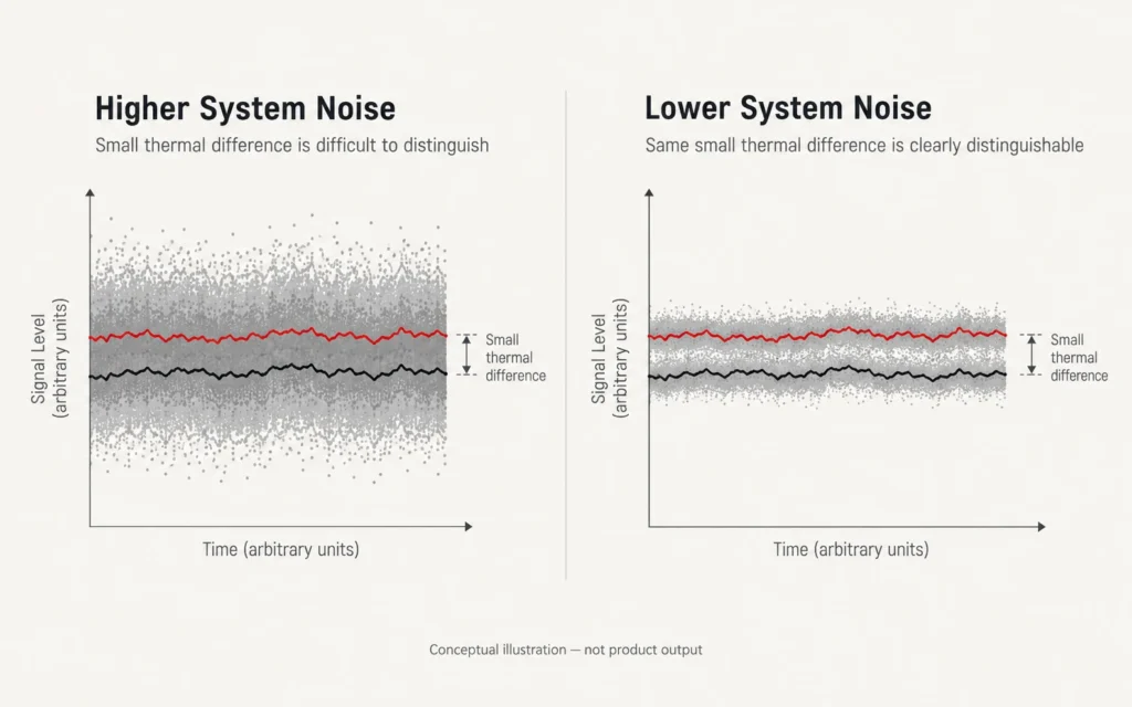
    If the thermal difference between two parts of a scene is large compared with the system noise, separating them is relatively easy.

    If their thermal signals are very close together, system noise becomes more significant.

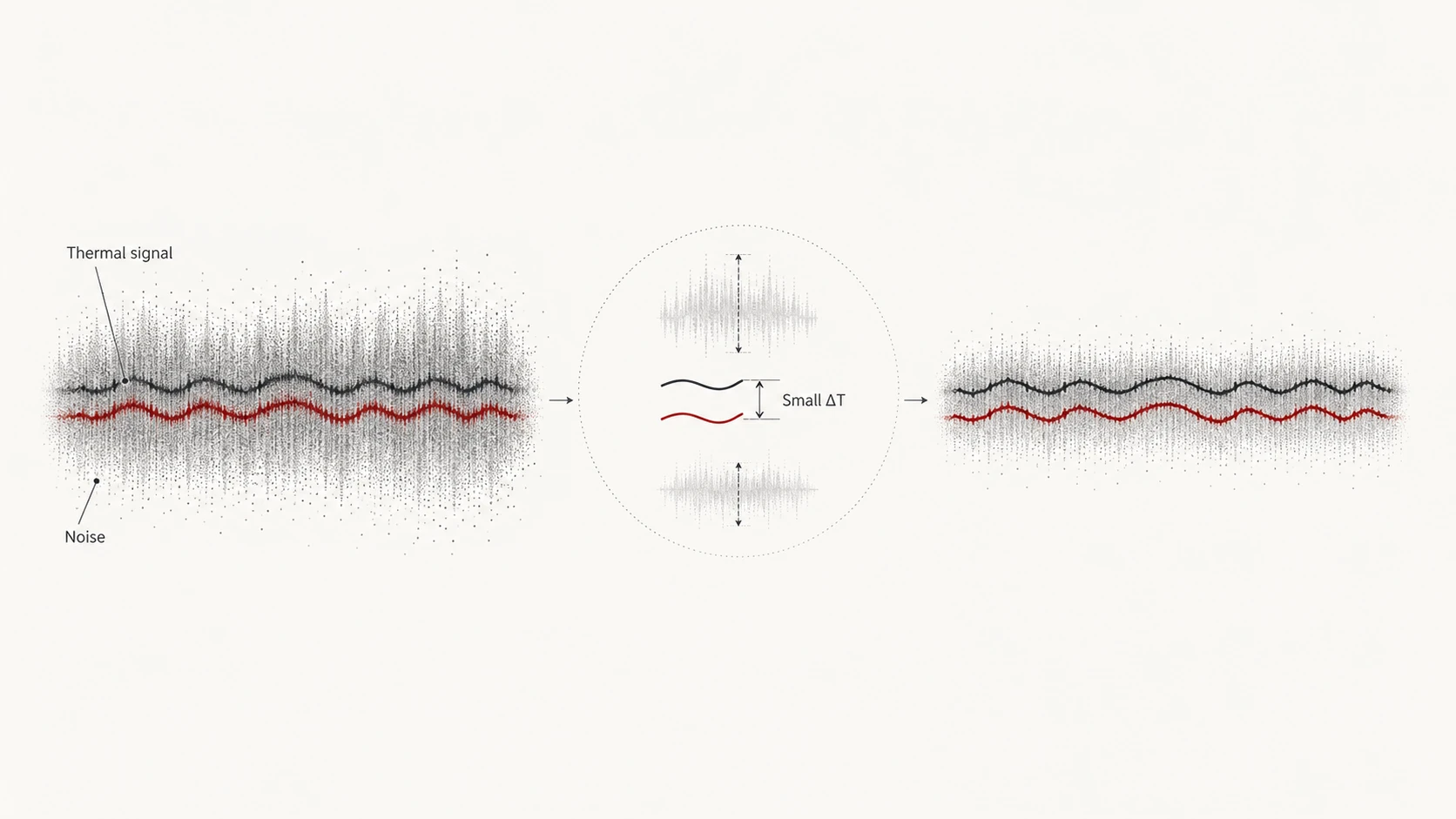
    A lower NETD indicates that smaller thermal differences can rise above that noise level under the specified test conditions.

    This is why NETD is often most noticeable in low-contrast thermal scenes, not necessarily in scenes where the target is already much warmer or colder than the background.

    For a deeper explanation of the detector itself, see our guide to thermal imaging FPA and microbolometers.

    Conceptual diagram showing how lower noise helps distinguish small thermal signal differences

    Lower mK Does Not Mean Higher Detector Resolution

    NETD and detector resolution describe different characteristics.

    Detector resolution tells you how many native sensing elements are available.

    For example:

    • 384 × 288 = 110,592 detector elements
    • 640 × 512 = 327,680 detector elements

    NETD instead describes thermal sensitivity relative to system noise.

    A useful distinction is:

    SpecificationPrimarily describes
    Detector resolutionNumber of native spatial samples
    Pixel pitchPhysical detector geometry
    NETDThermal sensitivity relative to noise
    Field of viewAngular scene coverage
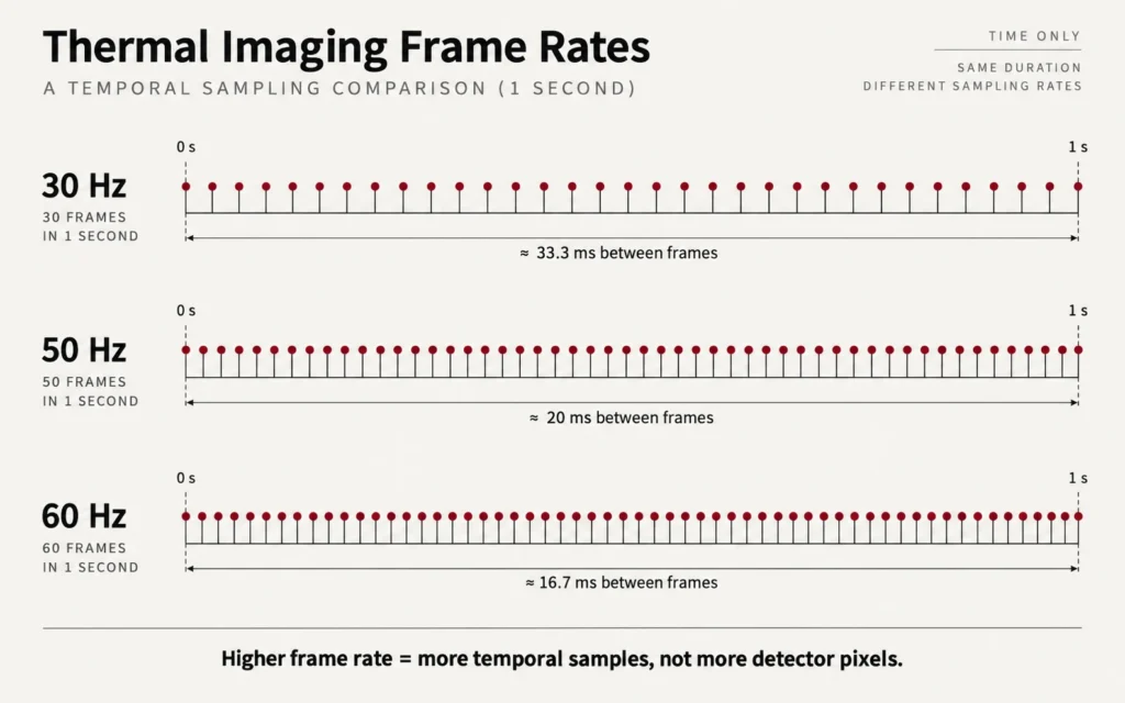
    Frame rateTemporal sampling

    A 640 × 512 detector does not automatically have a lower NETD than a 384 × 288 detector.

    Likewise, a lower-resolution detector can have strong thermal sensitivity.

    The specifications must be compared separately before evaluating how they work together.

    What Does an 18 mK NETD Specification Actually Tell You?

    An 18 mK value can indicate very high thermal sensitivity when it has been measured and specified under appropriate conditions.

    What it does not establish on its own is:

    • detector resolution;
    • field of view;
    • target identification distance;
    • lens quality;
    • digital zoom performance;
    • display resolution;
    • atmospheric performance;
    • temperature-measurement accuracy.

    This is why <18mK should not be treated as a universal dividing line between “good” and “bad” thermal imaging devices.

    Commercial thermal systems exist across a range of NETD values, resolutions, lenses, and applications.

    The useful question is not:

    “Is it below 18 mK?”

    but:

    “What NETD does this system achieve, under what conditions, and how does that sensitivity fit the intended application?”

    Test Conditions Matter When Comparing NETD

    NETD values should not be compared without understanding how they were obtained.

    One particularly important variable is lens f-number.

    The f-number affects how much infrared energy reaches the detector. A faster optical system can deliver more infrared energy to the focal plane than a slower one, affecting overall system sensitivity.

    For this reason, thermal-camera NETD specifications are often referenced or normalized to a stated f-number such as F/1.0. Teledyne FLIR specifically notes that lens f-number changes thermal-system NETD and that normalization is necessary for fair comparisons.

    Lens transmission also matters.

    Other relevant conditions can include:

    • scene or target temperature used during testing;
    • detector operating conditions;
    • integration and calibration method;
    • whether the quoted value belongs to the detector, camera core, or complete system;
    • processing configuration.

    FLIR also recommends paying attention to the temperature at which sensitivity is specified rather than comparing numbers measured under different conditions as though they were equivalent.

    Detector NETD and System NETD Are Not Always the Same Thing

    A detector specification describes the sensing component.

    A finished thermal device adds:

    • optics;
    • readout electronics;
    • calibration;
    • signal processing;
    • display processing;
    • mechanical and thermal design.

    The performance of the complete system can therefore differ from a detector-level value.

    When comparing products, determine whether the published NETD refers to:

    detector / sensor

    or:

    complete imaging system under specified conditions.

    If the datasheet does not make this clear, the numbers should be treated cautiously.

    Why Lower NETD Helps Most in Low-Contrast Scenes

    Imagine a target whose temperature differs greatly from the background.
    The thermal separation is already strong, so even a system with moderate sensitivity may display a clear target boundary.
    Now imagine the target and background temperatures becoming much closer.
    The available thermal contrast falls.
    In that situation, system noise represents a larger fraction of the useful signal.
    A lower-NETD imaging system can preserve smaller thermal differences relative to its noise level, potentially producing more usable tonal separation in a low-contrast scene.
    This is the practical reason thermal sensitivity matters.
    It does not create new spatial detail.
    It helps preserve subtle thermal contrast that might otherwise be obscured by noise.

    NETD and Image Detail Are Not the Same Thing

    A low NETD can help reveal small temperature differences across surfaces.

    But spatial detail depends heavily on other factors.

    Suppose two adjacent parts of a distant target fall onto the same detector pixel.

    Even if the sensor has excellent NETD, it cannot spatially separate those two structures because the detector does not sample them independently.

    Conversely, a high-resolution detector may provide many spatial samples but still produce a noisy or low-contrast image when the thermal differences in the scene are very small.

    This is why:

    resolution tells you how finely the scene is sampled

    while:

    NETD tells you how sensitively small thermal differences can be distinguished relative to noise

    Neither replaces the other.

    Pixel Pitch Does Not Determine NETD by Itself

    Pixel pitch and NETD are also different specifications.

    Pixel pitch describes the physical spacing between neighboring detector elements.

    Smaller pixels affect detector geometry, IFOV, and optical-system design.

    But a 12μm detector does not automatically have a lower NETD than a 17μm detector.

    Thermal sensitivity also depends on detector material, pixel structure, fill factor, thermal isolation, readout electronics, optics, calibration, and processing.

    This is why pixel pitch should not be used as a shortcut for thermal sensitivity.

    For the full geometry discussion, see 12μm pixel pitch in thermal imaging.

    Does Lower NETD Increase Detection Range?

    Potentially, under some conditions—but not as a simple one-to-one rule.

    Detection range depends on whether enough useful target signal reaches the system and whether that signal can be distinguished from the background and system noise.

    Lower NETD can help when target-to-background thermal contrast is weak.

    However, practical DRI performance also depends on:

    • target size;
    • detector resolution;
    • pixel pitch;
    • focal length;
    • field of view;
    • optics;
    • atmospheric transmission;
    • image processing;
    • target-to-background contrast.

    A lower NETD therefore should not be converted directly into a fixed increase in meters or yards.

    For example:

    “18 mK means X% more detection range than 35 mK”

    is not a defensible general rule without a controlled comparison of the entire imaging system and test conditions.

    For the full range discussion, see our guide to thermal detection, recognition, and identification.

    NETD Cannot Override Atmospheric Attenuation

    Thermal imaging does not depend on visible illumination, but infrared radiation still has to travel through the atmosphere before reaching the detector.

    Humidity, fog, rain, snow, and atmospheric path length can reduce target contrast or attenuate the infrared signal.

    FLIR notes that humidity can reduce atmospheric infrared transmission, while fog and rain can significantly reduce thermal-imaging range as water droplets absorb and scatter radiation. In severe fog, atmospheric transmission itself can become the dominant limitation.

    Lower NETD may help the imaging system make better use of weak thermal contrast that still reaches the detector.

    It cannot recover information that has been removed by severe atmospheric attenuation.

    For that reason, avoid claims such as:

    “low NETD sees through dense fog”

    or:

    “sub-18 mK eliminates weather limitations.”

    A more accurate statement is:

    lower NETD can be beneficial in difficult, low-contrast conditions, while atmospheric transmission still limits the signal available to the system.

    What About “Thermal Washout”?

    The term “thermal washout” is often used informally to describe scenes in which target and background temperatures become similar and visible thermal contrast decreases.

    This can occur during environmental transitions such as:

    • warm ground after solar heating;
    • changing ambient temperature;
    • high humidity;
    • precipitation;
    • backgrounds with similar surface temperatures.

    A lower NETD can help preserve smaller temperature differences in these scenes.

    But the image still depends on actual target-to-background contrast.

    NETD cannot create a temperature difference that does not exist.

    Does Lower NETD Make Digital Zoom Better?

    Not directly.

    Digital zoom enlarges image data that has already been captured by the detector.

    If the original image contains noise, enlarging it can make that noise more visible.

    A lower-NETD system may begin with a cleaner low-contrast thermal signal under comparable conditions, which can help the image remain more usable when viewed at higher digital magnification.

    But NETD does not increase native detector resolution.

    Digital zoom still does not create additional physical detector samples.

    Image processing and super-resolution may change how the enlarged image is presented, but those functions must be evaluated separately from native NETD.

    Image Processing Can Change the Appearance of NETD Performance

    The image shown on the display is not raw detector data.

    Thermal devices normally apply processing such as:

    • non-uniformity correction;
    • bad-pixel correction;
    • automatic gain control;
    • noise reduction;
    • local contrast enhancement;
    • sharpening;
    • palette mapping;
    • temporal filtering.

    Advanced processing can make an image look cleaner or more detailed.

    But a visually smooth image does not automatically prove a lower detector NETD.

    Heavy noise reduction can also remove fine temporal or spatial detail if it is poorly tuned.

    This is why still-image comparisons should not be used to infer NETD unless the devices and processing settings are controlled.

    For more on computational enhancement, see our guide to AI processing in thermal scopes.

    Display Resolution Does Not Improve NETD

    A higher-resolution OLED can improve presentation quality and interface readability.

    It cannot change the thermal sensitivity of the detector.

    Likewise, increasing display brightness or contrast does not improve the underlying NETD.

    The display is the final presentation layer.

    NETD is determined earlier in the imaging chain.

    This distinction matters because product specifications often place detector resolution, display resolution, and NETD next to each other even though they describe different components.

    NETD Should Be Read as Part of a Complete System

    A strong thermal imaging system balances multiple characteristics.

    NETD matters because thermal sensitivity determines how effectively subtle temperature differences can rise above system noise.

    But it works together with:

    • detector resolution;
    • pixel pitch;
    • optics;
    • focal length;
    • f-number;
    • field of view;
    • focus;
    • calibration;
    • frame rate;
    • processing;
    • display.

    A lower NETD cannot compensate for every weakness elsewhere in the imaging chain.

    For example, excellent sensitivity cannot recover spatial detail that the optical system never resolved onto the detector.

    Likewise, excellent resolution cannot fully compensate for a scene in which the thermal signal is buried in noise.

    This system-level view is central to understanding what defines a high-end thermal scope.

    Yubeen thermal imaging scope illustrating thermal image processing technology

    How to Compare NETD Between Thermal Devices

    When comparing two specification sheets, use this sequence.

    1. Confirm what the NETD value refers to.
      Detector, core, or complete imaging system?
    2. Check the stated test temperature.
      Do not assume values measured under different conditions are directly equivalent.
    3. Check lens f-number.
      Optical speed affects system sensitivity.
    4. Check whether the specification is normalized.
      Some values may be referenced to conditions such as F/1.0.
    5. Compare native detector resolution separately.
      NETD does not tell you how many spatial samples are available.
    6. Compare pixel pitch separately.
      Pixel geometry is not a substitute for thermal sensitivity.
    7. Check field of view and focal length.
      They determine viewing geometry and target sampling.
    8. Review processing modes.
      Heavy denoising or contrast processing can strongly affect displayed appearance.
    9. Look for controlled image comparisons.
      Same scene, same environmental conditions, similar FOV, comparable focus, and known settings are far more useful than unrelated screenshots.
    10. Match sensitivity to the intended use.
      Very low NETD may be particularly valuable when low thermal contrast is common, while another application may place more weight on resolution, FOV, size, or runtime.

    Is <18 mK a “Gold Standard”?

    It is better to avoid treating one NETD value as a universal industry threshold.

    A sub-18 mK specification represents very high thermal sensitivity when measured under appropriate and comparable conditions.

    That can be technically valuable.

    But the number does not automatically make a complete thermal device superior to every system with a higher NETD value.

    A device with:

    • lower NETD,
    • unsuitable FOV,
    • insufficient spatial resolution,
    • poor optics,
    • or poorly tuned processing

    may still be less appropriate for a particular application than a well-balanced alternative.

    NETD should therefore be interpreted as one important system specification, not as a pass/fail badge.

    What Should You Verify on a Product Datasheet?

    Before using a NETD figure to compare products, check:

    • NETD value;
    • test temperature;
    • lens f-number;
    • whether it is detector, core, or system NETD;
    • detector resolution;
    • pixel pitch;
    • focal length;
    • field of view;
    • frame rate;
    • display resolution;
    • processing mode used for demonstrations;
    • any qualifying conditions or footnotes.

    If the exact test conditions are not published, avoid assuming that two different manufacturers’ NETD numbers are perfectly comparable.

    Lower NETD Is Valuable—But Context Makes It Meaningful

    NETD is one of the most useful thermal-imaging specifications because it describes sensitivity to small thermal differences relative to system noise.

    Lower values are generally preferable when the measurement conditions are comparable.

    But the value becomes meaningful only when it is considered alongside detector resolution, optics, f-number, field of view, processing, and the actual thermal contrast of the scene.

    The correct conclusion is therefore not:

    “Every thermal device must be below 18 mK.”

    It is:

    “Understand the NETD value, understand how it was measured, and evaluate whether the complete system matches the intended conditions.”

    Once those requirements are clear, you can compare the current Yubeen thermal imaging range using the verified specifications of the exact current products.

    FAQ

    Is Lower NETD Better?

    Under comparable test conditions, a lower NETD generally indicates greater thermal sensitivity and an improved ability to distinguish smaller thermal differences relative to system noise.

    Does 18 mK Mean the Device Can Accurately Measure 0.018°C?

    No. An 18 mK value corresponds to a 0.018 K temperature interval, but NETD is a noise-equivalent sensitivity metric. It should not be interpreted as general temperature-measurement accuracy or a guarantee of resolving every 0.018°C field difference.

    Is NETD More Important Than Detector Resolution?

    Neither replaces the other. NETD describes thermal sensitivity, while detector resolution describes spatial sampling. The relative importance depends on the scene and intended use.

    Does Lower NETD Increase Detection Range?

    It can help in low-contrast conditions, but it does not create a fixed increase in detection distance. DRI performance also depends on target size, resolution, optics, field of view, atmosphere, contrast, and processing.

    Can a Low-NETD Thermal Device See Through Fog?

    Not literally. Lower NETD can help preserve weak thermal contrast that reaches the detector, but fog, humidity, and rain can attenuate infrared radiation and reduce practical range.

    Does a 12μm Detector Automatically Have Lower NETD Than a 17μm Detector?

    No. Pixel pitch and NETD are different specifications. Thermal sensitivity depends on the complete detector and imaging-system design, not pixel pitch alone.

  • How Weather Affects Thermal Imaging: Fog, Rain, Snow, and Cold Explained

    How Weather Affects Thermal Imaging: Fog, Rain, Snow, and Cold Explained

    Understanding how weather affects thermal imaging is important because fog, rain, humidity, snow and cold can all change thermal contrast and practical detection range.

    Thermal imaging does not depend on visible illumination, which is why it can remain useful when conventional optics become difficult to use after sunset or in complete darkness.

    Weather, however, is a different issue.

    Fog, rain, humidity, snow, cold air, and changing surface temperatures can all affect the infrared energy traveling from the scene to the detector. Some conditions reduce atmospheric transmission. Others reduce the thermal contrast between a target and its background. Water on the lens can introduce another layer of image degradation.

    The result is that thermal imaging often remains useful in conditions where visible imaging struggles, but it should not be described as unaffected by weather.

    If you are comparing complete products rather than environmental behavior alone, start with our guide on how to choose a thermal imaging scope.

    Why Thermal Imaging Works Without Visible Light

    Conventional visible-light optics depend on light being reflected from the scene and entering the eye or camera.

    Thermal imaging works differently.

    Objects above absolute zero emit electromagnetic radiation, including infrared radiation. A thermal detector records differences in the infrared energy reaching the focal plane and converts those differences into image data.

    Many uncooled thermal imagers operate in the long-wave infrared region, commonly associated with approximately 7–14μm detector response, while atmospheric transmission is particularly useful in portions of the LWIR window around 8–12μm.

    Because this process does not require visible illumination, darkness itself does not prevent thermal image formation.

    But infrared energy still has to pass through the atmosphere before it reaches the detector.

    That distinction is the key to understanding weather performance.

    For more on the detector and focal plane itself, see our guide to thermal imaging FPA and microbolometers.

    The Atmosphere Is Part of the Imaging System

    A thermal imager does not receive all of the infrared energy emitted by a distant target.

    Some energy is absorbed or scattered by the atmosphere, while the atmosphere itself also contributes infrared radiation.

    The longer the path between target and detector, the more atmospheric conditions can matter.

    Relative humidity, atmospheric temperature, aerosols, fog droplets, rain, snow, and other obscurants can all change effective transmission.

    FLIR’s radiometric guidance explicitly treats distance, atmospheric temperature, and relative humidity as variables that can affect the infrared signal reaching a camera.

    This is why a quoted detection range measured in clear, dry conditions should not automatically be expected in heavy fog or rain.

    Fog: Thermal Can Outperform Visible Light, but It Does Not “See Through” Fog

    Fog is made of suspended water droplets.

    Visible light is strongly scattered by those droplets, which is why headlights and conventional cameras can perform poorly in fog.

    Thermal infrared can perform better under some fog conditions because transmission in the LWIR band can be more favorable than transmission in the visible band.

    That advantage is real.

    But it has limits.

    FLIR’s atmospheric modeling shows that thermal imaging can outperform visible imaging in lighter and moderate fog, while dense fog can reduce the advantage dramatically. Under sufficiently dense fog, atmospheric transmission itself becomes the dominant limitation.

    Therefore the technically accurate statement is:

    thermal imaging may retain useful range in some fog conditions where visible imaging is more severely degraded.

    Not:

    thermal imaging sees through fog.

    Fog Density Matters

    There is no single “fog performance” value.

    Fog differs in:

    • droplet size;
    • droplet density;
    • aerosol type;
    • humidity;
    • climate;
    • atmospheric path length.

    A light mist and a dense fog bank are not equivalent optical environments.

    This is why comparing products from one fog photograph can be misleading unless the conditions are controlled.

    Humidity Can Reduce Long-Range Transmission

    Even without visible fog, humid air can affect infrared transmission.

    Water vapor has strong infrared absorption characteristics, and transmission loss becomes increasingly important over longer paths.

    FLIR notes that higher humidity can increase atmospheric attenuation and that clear, dry winter conditions can provide better long-range transmission than humid conditions.

    For short distances, the effect may be relatively small.

    At longer distances, especially when target contrast is already weak, atmospheric attenuation becomes more important.

    This is one reason long-range thermal performance cannot be predicted from detector resolution alone.

    Rain Reduces Contrast in More Than One Way

    Rain can affect thermal imaging through several mechanisms.

    First, raindrops and moisture in the atmospheric path can scatter and absorb infrared energy, reducing target-to-background contrast.

    Second, rain changes the thermal state of surfaces.

    Wet ground, vegetation, structures, and animals can move toward similar surface temperatures, reducing thermal contrast even when the detector itself is functioning normally.

    Third, water droplets on the front lens can degrade image quality.

    FLIR notes that the effect of water droplets on a thermal lens depends on factors including coverage, focus position, and focal length.

    This means heavy rain should not be described as merely a software problem that can be “corrected” by image enhancement.

    Some of the information has physically been reduced before it reaches the detector.

    Snow Has Both Contrast Advantages and Transmission Limits

    Snow-covered environments can sometimes produce strong thermal contrast.

    Fresh snow is often much colder than warm animals, people, machinery, or recently heated objects.

    That can make warm targets stand out clearly.

    However, snow does not guarantee strong performance.

    Falling snow introduces particles into the atmospheric path.

    Wet snow and moisture can change surface temperatures.

    Accumulated snow may hide parts of an object.

    And snow or moisture on the lens can reduce image quality.

    The useful question is therefore not:

    “Does thermal work in snow?”

    but:

    “How much usable target contrast reaches the detector under the actual snow, moisture, distance, and temperature conditions?”

    Cold Weather Can Increase Contrast—but Can Also Stress the Device

    Cold environments can sometimes improve target-to-background contrast when the target remains substantially warmer than its surroundings.

    FLIR notes that colder ambient conditions can increase temperature difference between a warmer target and its environment under some circumstances.

    But cold-weather imaging also introduces practical issues.

    Battery performance can fall at low temperatures.

    Displays and electronics may have specified operating limits.

    Rapid transitions between warm and cold environments can cause detector drift or condensation.

    For this reason, the exact operating-temperature specification of the product still matters.

    Do not assume every thermal device behaves identically in sub-zero conditions.

    Rapid Temperature Changes Can Affect Image Stability

    Moving a thermal device quickly between significantly different ambient temperatures can temporarily change detector and housing temperatures.

    That can affect calibration and image stability until the system reaches a more stable thermal condition.

    FLIR specifically notes that rapid transitions from warm to cold or cold to warm can produce temperature drift and detector-response changes.

    For observational thermal optics, the exact behavior depends on the hardware and calibration strategy.

    This is one reason field performance should be judged after the device has stabilized rather than immediately after a large environmental transition.

    Thermal Contrast Can Disappear Even in Clear Weather

    Bad weather is not the only reason a thermal image can become difficult to interpret.

    A clear scene can still have low thermal contrast.

    For example, after prolonged solar heating, ground, vegetation, rocks, and structures may approach similar apparent surface temperatures.

    Around environmental transitions, the target and background can sometimes become thermally similar.

    When that happens, scene contrast falls even though the atmosphere is clear.

    This is sometimes informally described as thermal crossover or low-contrast thermal conditions.

    The important point is:

    thermal image quality depends on temperature contrast as well as atmospheric transmission.

    NETD Matters Most When Contrast Is Weak

    NETD describes thermal sensitivity relative to system noise.

    When a target is much warmer or colder than the background, contrast is already strong.

    When target and background temperatures are close, smaller thermal differences become harder to preserve.

    A lower NETD can help the imaging system distinguish weaker thermal differences under comparable measurement conditions.

    But lower NETD does not eliminate atmospheric attenuation.

    It cannot recreate infrared information that fog, rain, or another obstruction prevented from reaching the detector.

    For a full explanation, see NETD in thermal imaging.

    Detector Resolution Still Matters in Bad Weather

    Atmospheric degradation and thermal sensitivity do not remove the need for spatial detail.

    Detector resolution determines how many native spatial samples are available.

    A higher-resolution detector can provide more spatial information when optical conditions and field of view are comparable.

    But degraded atmosphere can reduce target contrast before that information reaches the detector.

    This means:

    more pixels cannot completely compensate for poor atmospheric transmission.

    Likewise:

    strong atmospheric transmission does not compensate for insufficient spatial sampling.

    The two factors solve different problems.

    Pixel Pitch Does Not Make a Device Weather-Proof

    Pixel pitch influences detector geometry and angular sampling.

    It does not determine atmospheric transmission.

    A 12μm detector does not automatically perform better in fog than a 17μm detector.

    Weather performance still depends on:

    • wavelength band;
    • atmosphere;
    • optics;
    • detector sensitivity;
    • resolution;
    • focal length;
    • field of view;
    • processing;
    • target contrast.

    Pixel pitch should therefore not be used as a shortcut for weather capability.

    Lens Quality and F-Number Still Matter

    The objective lens determines how much useful infrared energy reaches the detector.

    Lens transmission, focal length, focus quality, coatings, and f-number all influence the signal delivered to the focal plane.

    In difficult conditions, where the available target signal may already be reduced, poor optical transmission becomes even more significant.

    This does not mean one lens specification can overcome bad weather.

    It means the optical system remains part of the total performance chain.

    Water, Condensation, and the Front Lens Matter

    Weather does not affect only the atmosphere between the target and the device.

    It can also affect the optics directly.

    Water droplets, condensation, frost, mud, or snow on the objective surface can reduce image quality.

    FLIR’s technical guidance notes that the impact of water droplets depends partly on focus and focal length, as well as how much of the lens is covered.

    This is a practical maintenance issue rather than a detector specification.

    Keep the front optic clean according to the manufacturer’s instructions and avoid wiping abrasive debris across the surface.

    Image Processing Can Help—but It Cannot Restore Missing Signal

    Modern thermal devices may apply:

    • non-uniformity correction;
    • automatic gain control;
    • noise reduction;
    • local contrast enhancement;
    • sharpening;
    • temporal filtering;
    • super-resolution or other advanced processing.

    These functions can improve the presentation of weak thermal information.

    But software operates on data that has already reached the detector.

    If severe fog or rain has attenuated much of the useful target signal, processing cannot reconstruct every lost physical measurement with certainty.

    This is why claims such as:

    “AI removes fog”

    or:

    “image enhancement restores full range in rain”

    should be treated cautiously.

    For more on computational enhancement, see AI processing in thermal scopes.

    Display Quality Does Not Change Atmospheric Transmission

    A high-resolution OLED can make the processed image easier to view.

    It does not change the infrared signal that passed through the atmosphere.

    Likewise, changing palette or display contrast can make certain details easier to see without changing the underlying detector data.

    Display quality matters to usability.

    It should not be confused with weather penetration or detector sensitivity.

    Weather Can Change DRI Range

    Detection, recognition, and identification all depend on usable target information.

    Weather can reduce that information by:

    • attenuating infrared radiation;
    • reducing target-to-background contrast;
    • obscuring parts of the target;
    • degrading lens transmission;
    • adding noise or clutter to the scene.

    As a result, the practical DRI range in fog or heavy rain can be shorter than a range measured under clear conditions.

    This is why detection-range specifications should be interpreted together with the conditions under which they were calculated or tested.

    For the full DRI discussion, see our guide to thermal detection, recognition, and identification.

    What Specifications Matter Most in Difficult Weather?

    Weather performance is a system result.

    Diagram summarizing how fog, rain, humidity, snow, and cold affect thermal imaging

    Useful specifications and characteristics include:

    FactorWhy it matters in poor conditions
    NETDHelps preserve small thermal differences relative to noise
    Detector resolutionDetermines available spatial samples
    Lens transmissionInfluences how much infrared energy reaches the detector
    F-numberInfluences optical throughput and system sensitivity
    Focal length / FOVDetermines scene coverage and angular target sampling
    FocusAffects how effectively detail reaches the detector
    Image processingCan improve presentation of weak or noisy data
    IP ratingDescribes environmental sealing for the exact product
    Operating temperatureDefines the supported ambient range
    Battery systemAffects practical runtime, especially in cold weather

    No single row guarantees strong bad-weather performance.

    Environmental Ratings Are Product-Specific

    It is reasonable to check IP rating, operating temperature, storage temperature, and mechanical durability for field equipment.

    But these specifications must be taken from the exact current model.

    Do not assume that every product in a range has:

    • the same IP rating;
    • the same cold-weather limit;
    • the same shock rating;
    • the same battery behavior.

    And avoid vague terms such as “weather-proof” or “military-grade” unless a defined standard supports them.

    For broader ownership and handling issues, see our guide to thermal scope reliability.

    A Real Product Still Needs to Be Judged as a Complete System

    A thermal product used in wet, cold, foggy, or low-contrast conditions should be evaluated from the full system rather than one headline specification.

    Detector resolution determines spatial sampling.

    NETD influences sensitivity.

    The lens controls infrared transmission and viewing geometry.

    Atmospheric conditions determine how much target signal survives the path.

    Image processing affects how the data is presented.

    And the enclosure, battery, and operating-temperature design determine whether the device remains practical in the environment.

    Current Yubeen thermal imaging product shown as a field-use example

    A current Yubeen thermal imaging product should therefore be evaluated from its verified detector, optics, environmental ratings, power system, and intended application rather than from a general “all-weather” claim.

    How to Evaluate Thermal Performance in Bad Weather

    When comparing devices, use this sequence:

    1. Define the weather condition.
      Light fog, dense fog, rain, snow, humidity, and cold are different problems.
    2. Define the expected distance.
      Atmospheric loss increases with path length.
    3. Check target size and thermal contrast.
      A large, high-contrast target is easier than a small low-contrast one.
    4. Compare native detector resolution.
      Do not confuse display resolution with detector resolution.
    5. Check NETD under stated conditions.
      Sensitivity can matter strongly in low-contrast scenes.
    6. Check lens and field of view.
      Viewing geometry still controls target sampling.
    7. Check current environmental ratings.
      IP and operating-temperature limits must belong to the exact model.
    8. Look at lens exposure.
      Rain, snow, condensation, or contamination on the front optic can affect image quality.
    9. Treat image processing separately.
      Processing may improve presentation but cannot eliminate atmospheric attenuation.
    10. Compare field results only under similar conditions.
      Two screenshots taken in different weather are not a controlled comparison.

    What Thermal Imaging Can—and Cannot—Do in Bad Weather

    A useful summary is:

    Thermal imaging can:

    • operate without visible illumination;
    • retain useful contrast in some fog, rain, or snow conditions;
    • outperform visible imaging in certain low-visibility environments;
    • reveal small thermal differences when detector sensitivity is sufficient.

    Thermal imaging cannot:

    • make dense fog transparent;
    • see through solid vegetation or other opaque objects;
    • eliminate atmospheric attenuation;
    • guarantee the same range in every weather condition;
    • recover physical signal that never reached the detector.

    This distinction is more useful than calling thermal imaging “all-weather.”

    FAQ

    Can Thermal Imaging Work in Complete Darkness?

    Yes. Thermal imaging does not require visible illumination because it detects infrared radiation from the scene. However, useful image contrast still depends on differences in thermal signal between objects and backgrounds.

    Can Thermal Imaging See Through Fog?

    Sometimes it can outperform visible imaging in light or moderate fog, particularly in the LWIR band. Dense fog can still strongly attenuate infrared radiation and reduce range, so “see through fog” is too absolute.

    Does Rain Stop Thermal Imaging From Working?

    Not necessarily, but rain can reduce atmospheric transmission, lower target-to-background contrast, and place water on the front lens. Heavy rain can therefore shorten practical range and reduce image quality.

    Does Snow Improve Thermal Contrast?

    It can when warm targets are viewed against a cold snow-covered background. Falling snow, wet surfaces, atmospheric loss, and lens contamination can still reduce performance.

    Is Cold Weather Better for Thermal Imaging?

    Cold backgrounds can sometimes increase thermal contrast for warmer targets, but cold weather can also affect batteries, electronics, condensation, and device operating limits. The exact product specification should be checked.

    Does Lower NETD Make a Thermal Scope Weather-Proof?

    No. Lower NETD can help distinguish weaker thermal differences under comparable conditions, but it cannot eliminate atmospheric attenuation or physical obstruction.

  • Thermal Imaging FPA Explained: Microbolometers, Resolution, and Refresh Rate

    Thermal Imaging FPA Explained: Microbolometers, Resolution, and Refresh Rate

    A thermal imaging FPA is the focal plane array that converts incoming infrared energy into detector data used to build a thermal image. Detector resolution tells you how many sensing elements are available. Pixel pitch describes their physical spacing. NETD relates to thermal sensitivity. Refresh rate describes how frequently new image frames are produced.

    At the center of that chain is the Focal Plane Array, or FPA.

    In many modern uncooled thermal imaging systems, the FPA is an array of microbolometer detector elements positioned at the focal plane of the infrared optical system. Understanding what happens at this stage makes it much easier to interpret the specifications that appear later in a thermal product datasheet.

    For a broader introduction to thermal image formation and basic specifications, see our thermal imaging for beginners guide.

    What Is a Focal Plane Array?

    A Focal Plane Array is a two-dimensional detector array positioned where the infrared optical system forms an image.

    Instead of scanning the scene with one detector element, an FPA contains many detector elements arranged in rows and columns. Each element samples infrared energy from a small part of the scene.

    In an uncooled microbolometer FPA, incoming infrared radiation is absorbed by very small thermally isolated detector structures. The absorbed energy causes a small temperature change, which changes an electrical property of the sensing material. Readout circuitry then converts those changes into electrical signals that can be processed into a thermal image. NIST describes the basic microbolometer process as infrared absorption heating a microbridge, followed by a temperature-dependent resistance change that is converted into an electrical signal.

    How a Microbolometer Pixel Works

    A typical microbolometer is not simply a miniature visible-light camera pixel.

    Its sensing structure is designed to absorb infrared radiation while remaining thermally isolated from the underlying readout electronics. Modern uncooled devices commonly use a suspended membrane connected to the readout circuit through narrow support structures.

    The simplified process is:

    1. Infrared radiation reaches the detector.
    2. The microbolometer absorbs part of that energy.
    3. Its temperature changes slightly.
    4. The temperature-sensitive material changes electrical resistance.
    5. Readout electronics measure the resulting electrical signal.
    6. Calibration and image processing convert the detector data into the image shown to the user.
    Diagram showing how an uncooled microbolometer pixel converts infrared energy into an electrical signal

    LYNRED similarly describes uncooled LWIR microbolometers as suspended structures containing thermoresistive material, with readout circuitry beneath the detector array.

    The FPA therefore provides the thermal measurements that form the basis of the image. It does not, by itself, determine how the final display will look.

    FPA Resolution: How Many Detector Elements Are There?

    Thermal detector resolution is normally written as a horizontal and vertical pixel count.

    For example:

    • 384 × 288 = 110,592 detector elements
    • 640 × 512 = 327,680 detector elements

    A 640 × 512 detector therefore contains almost three times as many sensing elements as a 384 × 288 detector.

    If two systems use comparable optics and cover the same field of view, the higher-resolution detector can sample the scene at more spatial locations.

    That can provide more information about small structures and target boundaries.

    But resolution alone does not determine final image quality or practical range. Lens quality, field of view, pixel pitch, thermal sensitivity, focus, atmospheric conditions and image processing still matter.

    Detector Resolution Is Not Display Resolution

    This distinction is important.

    A device may have:

    • one native detector resolution,
    • another processing resolution,
    • and a different display resolution.

    For example, displaying a 384 × 288 detector image on a higher-resolution OLED does not turn the thermal detector into a higher-resolution FPA.

    The display can present the image more smoothly or provide additional interface detail, but the original thermal measurement still comes from the native detector array.

    Likewise, interpolation or super-resolution does not change the physical detector pixel count.

    Pixel Pitch and FPA Resolution Work Together

    Resolution tells you how many detector elements exist.

    Pixel pitch tells you how far apart those elements are physically.

    Those two specifications should always be read separately.

    A 640 × 512 detector with 12μm pitch and a 640 × 512 detector with 17μm pitch contain the same number of detector elements, but their physical array dimensions are different.

    Pixel pitch also interacts with lens focal length to determine angular sampling, or IFOV.

    That is why comparing only detector resolution can miss an important part of the imaging geometry.

    For the full relationship between 12μm, 17μm, detector dimensions and IFOV, see our guide to 12μm pixel pitch in thermal imaging.

    What Does Refresh Rate Mean in Thermal Imaging?

    Refresh rate, frame rate or image frequency describes how often the thermal imaging system produces a new image frame.

    A system operating at:

    • 30 Hz produces about 30 new frames per second
    • 50 Hz produces about 50 new frames per second
    • 60 Hz produces about 60 new frames per second

    Expressed as time between frames, that is approximately:

    • 30 Hz → 33.3 ms per frame
    • 50 Hz → 20 ms per frame
    • 60 Hz → 16.7 ms per frame
    Diagram comparing 30 Hz, 50 Hz, and 60 Hz thermal imaging frame intervals

    A higher frame rate provides more temporal samples of a moving scene.

    That generally makes motion appear more continuous and can make panning or tracking moving objects easier.

    It does not add spatial resolution.

    A 384 × 288 detector running at 60 Hz still has 384 × 288 native detector elements.

    Likewise, a 640 × 512 detector running at 30 Hz still contains more spatial samples than a 384 × 288 detector running at 60 Hz.

    Resolution and frame rate describe different dimensions of performance.

    Refresh Rate Is Not the Same as Microbolometer Response Time

    Another important distinction is the difference between frame rate and detector response time.

    A microbolometer does not respond instantaneously to a change in incoming infrared radiation. Its thermal structure needs time to heat or cool toward the new condition.

    This behavior is often described by a thermal time constant.

    FLIR notes that the thermal time constant in some of its microbolometer cameras is approximately 7–12 ms and specifically warns that this should not be confused with detector integration time.

    That number is not a universal value for every thermal detector, but it illustrates the principle:

    how frequently frames are read out and how quickly each detector element responds are related system characteristics, but they are not the same specification.

    Why the Difference Matters

    Imagine a thermal system producing 60 frames per second.

    The frame interval is approximately 16.7 ms.

    That does not automatically mean the detector can perfectly resolve every thermal event occurring within that interval.

    If the detector’s thermal response is slow relative to scene motion or temperature change, the resulting image can still show temporal blur or reduced contrast on rapidly changing objects.

    High frame rate therefore cannot be evaluated completely independently from detector response characteristics.

    Sensor Frame Rate and Display Refresh Rate Are Also Different

    A third specification can create confusion: display refresh rate.

    The thermal detector may produce images at one frequency while the OLED or LCD display updates at another.

    For example, a display capable of refreshing at 60 Hz does not automatically mean the thermal detector is producing 60 unique thermal frames each second.

    If the detector pipeline supplies only 30 thermal frames per second, a faster display can show those frames smoothly, but it cannot create additional physical thermal measurements.

    When comparing products, distinguish between:

    1. detector / sensor image frequency,
    2. image-processing output frequency,
    3. display refresh rate.

    Whenever possible, the specification that matters for scene motion is the rate at which genuinely new thermal image data are available.

    Resolution and Refresh Rate Solve Different Problems

    It is useful to think about resolution and refresh rate along two different axes.

    SpecificationPrimarily describesIt does not directly tell you
    Detector resolutionSpatial samplingMotion update rate
    Pixel pitchDetector geometry / angular sampling with the lensThermal sensitivity by itself
    NETDSensitivity to small temperature differences under defined conditionsDetector resolution
    Image frequency / frame rateTemporal samplingSpatial detail
    Thermal time constantDetector response dynamicsNumber of detector pixels
    Display resolutionHow the processed image is presentedNative FPA resolution

    This is why one specification should not be used as a substitute for another.

    A higher-resolution detector does not automatically have a higher refresh rate.

    A higher refresh rate does not automatically produce more spatial detail.

    And a smaller pixel pitch does not automatically guarantee lower NETD.

    What Role Does NETD Play?

    NETD, or Noise Equivalent Temperature Difference, is another detector-related specification that is frequently mixed together with resolution.

    NETD describes the ability of a thermal imaging system to distinguish small differences in thermal signal under defined test conditions.

    Lower NETD generally indicates greater thermal sensitivity under those conditions.

    But NETD is not another form of resolution.

    Two detectors can have the same resolution and different NETD values.

    Two detectors can also have similar NETD specifications but different resolutions, pixel pitches or optical configurations.

    A useful way to think about the distinction is:

    • Resolution: how many spatial samples are available
    • NETD: how small a thermal difference the system can distinguish under defined conditions
    • Frame rate: how often the scene is sampled in time

    All three can affect the experience of using a thermal imaging device, but they measure different things.

    NETD should also not be interpreted as proof that a device can “see through” fog, rain, vegetation or other physical obstructions. Atmospheric transmission and target-to-background contrast still affect the infrared signal reaching the detector.

    From Raw FPA Data to the Displayed Image

    The detector output is only the beginning of the imaging pipeline.

    Raw FPA data normally requires processing before it becomes the thermal image shown on the display.

    Depending on the device, the processing chain may include:

    • detector calibration,
    • non-uniformity correction,
    • bad-pixel correction,
    • automatic gain control,
    • noise reduction,
    • contrast processing,
    • sharpening,
    • image scaling,
    • palette mapping,
    • digital zoom,
    • and, in some systems, neural-network or AI-assisted processing.

    This is why two devices using sensors with similar headline specifications can still produce visibly different output.

    The detector defines the available measurements. The optics determine how infrared energy reaches that detector. Processing determines how those measurements are corrected and presented.

    For more on the computational side of this pipeline, see AI processing in thermal scopes.

    Does Higher Resolution Always Mean a Better Thermal Image?

    No.

    Higher detector resolution is valuable because it provides more spatial samples, but image quality is a system result.

    Consider a higher-resolution detector paired with:

    • a poorly focused lens,
    • insufficient optical resolution,
    • high detector noise,
    • inappropriate image processing,
    • or an unsuitable field of view.

    The additional pixels do not automatically solve those problems.

    Conversely, a lower-resolution system with good optics, appropriate field of view, strong thermal sensitivity and well-tuned processing may perform very effectively for its intended application.

    This is why detector resolution should be treated as an important specification—not as a complete product ranking.

    Does a Higher Refresh Rate Always Mean Better Performance?

    No.

    A higher frame rate is most valuable when the scene or device is moving.

    For mostly stationary observation, the difference between two frame rates may be less important than detector resolution, field of view, NETD or optical design.

    Higher frame rates also require the detector, readout electronics and image-processing pipeline to handle more information per second.

    The correct frame rate therefore depends on the intended use rather than a universal threshold.

    Statements such as:

    “Anything below 50 Hz is inadequate”

    are too absolute.

    Commercial thermal imaging systems exist at many different frame rates for different applications. FLIR, for example, sells microbolometer systems ranging from single-digit image frequencies through 30 Hz and beyond, demonstrating that frame rate is an application-dependent design choice rather than a single quality threshold.

    How to Compare FPA Specifications Correctly

    When evaluating the detector section of a thermal imaging specification sheet, use the following order.

    1. Identify the detector type.
      Confirm whether the device uses an uncooled microbolometer or another detector architecture.
    2. Check native detector resolution.
      Use the actual FPA dimensions rather than display resolution or enhanced-output resolution.
    3. Check pixel pitch.
      Combine pitch with focal length and field of view when evaluating angular sampling.
    4. Compare field of view.
      The same detector resolution can behave very differently behind different lenses.
    5. Check image frequency or sensor frame rate.
      Do not substitute display refresh rate for sensor image frequency.
    6. Check NETD separately.
      Sensitivity and spatial resolution describe different characteristics.
    7. Check response time if the manufacturer publishes it.
      Do not assume frame rate alone defines detector response to fast thermal changes.
    8. Look at the optical system.
      Focal length, f-number, transmission and focus affect the infrared signal reaching the FPA.
    9. Consider image processing.
      Denoising, sharpening, calibration and super-resolution can change the displayed result.
    10. Compare real images under controlled conditions.
      Specifications are most useful when the scene, distance, lens settings, weather and display conditions are comparable.

    This same system-level approach is important when evaluating what defines a high-end thermal scope.

    FPA Specifications Should Be Read as a System

    The FPA is fundamental to thermal imaging, but it is not an isolated quality score.

    Resolution determines the number of native detector samples.

    Pixel pitch influences detector geometry and, together with focal length, angular sampling.

    NETD describes thermal sensitivity under specified conditions.

    Frame rate describes temporal sampling.

    Detector response time affects how quickly the sensing elements react to changing infrared energy.

    The lens determines what infrared information reaches the detector, while the processing pipeline determines how that information is corrected and displayed.

    A useful thermal specification sheet therefore should not be reduced to a single headline number.

    The most meaningful comparison comes from understanding how those specifications work together.

    FAQ

    What Does FPA Mean in Thermal Imaging?

    FPA stands for Focal Plane Array. It is the two-dimensional array of infrared detector elements located at the focal plane of the thermal optical system.

    Is a Microbolometer the Same as an FPA?

    Not exactly. A microbolometer is an individual thermal detector element or detector technology. An uncooled microbolometer FPA contains many microbolometer elements arranged as an imaging array.

    Is 640 × 512 Always Better Than 384 × 288?

    No. A 640 × 512 detector contains more native detector elements and can provide finer spatial sampling under comparable optical conditions, but complete image performance also depends on pixel pitch, lens design, field of view, NETD, processing and other factors.

    Is 60 Hz Always Better Than 30 Hz?

    No. A higher frame rate provides more temporal samples and usually improves motion continuity, but whether that matters depends on the application. Frame rate does not increase native detector resolution or automatically improve thermal sensitivity.

    Is Display Refresh Rate the Same as Thermal Sensor Frame Rate?

    No. The display may refresh at a different frequency from the detector. A faster display cannot create additional thermal measurements if the detector and processing pipeline are producing fewer unique thermal frames.

    Does Lower NETD Mean Higher Resolution?

    No. NETD describes thermal sensitivity, while resolution describes the number of detector elements. They should be evaluated independently.

  • Thermal Clip-On Setup: Compatibility, Alignment, and Calibration Basics

    Thermal Clip-On Setup: Compatibility, Alignment, and Calibration Basics

    A thermal clip-on is designed to add thermal imaging capability in front of an existing day optic rather than replace the day optic completely.

    That architecture creates a different setup problem from mounting a dedicated thermal scope.

    The user is no longer dealing with one optical device. The complete viewing system now includes the day optic, thermal attachment, adapter or rail mount, mechanical alignment between the two devices, the thermal display, and any electronic image-alignment functions provided by the clip-on.

    A setup can therefore be mechanically secure while still being poorly aligned optically.

    The most useful way to understand thermal clip-on setup is to separate compatibility, mechanical alignment, optical alignment, and electronic calibration.

    If you first need to understand rail and mount interfaces, see our guide to thermal scope mounting standards.

    What Is a Thermal Clip-On?

    A thermal clip-on is a thermal imaging device designed to work together with another optic rather than function only as a standalone thermal sight.

    In a common front-mounted configuration, the thermal unit is placed ahead of the existing day optic.

    The thermal device:

    1. receives infrared information from the scene;
    2. forms and processes a thermal image;
    3. presents that image on its internal display;
    4. allows the day optic behind it to view that displayed thermal image.

    This architecture differs from a dedicated thermal scope, where the thermal detector, display, sighting interface, and viewing optics are integrated into one primary device.

    Commercial thermal clip-ons are commonly offered specifically for use in front of existing day optics.

    Clip-On Compatibility Starts With the Mounting Architecture

    Before considering calibration, first determine how the exact thermal attachment is designed to connect.

    Different clip-on systems may use:

    • a rail-mounted base;
    • a clamp attached to the objective housing of the day optic;
    • a dedicated adapter;
    • an insert ring sized for a particular objective diameter;
    • a manufacturer-specific mounting interface.

    These designs are not interchangeable.

    A clip-on made for a front rail position should not automatically be treated like an objective-lens adapter, and an objective adapter designed for one outside diameter should not be assumed to fit another.

    Manufacturer documentation is therefore the source of truth for the exact adapter and compatible day-optic dimensions.

    For example, commercial clip-on systems exist both as rail-mounted devices and as attachments that use dedicated objective adapters.

    Rail-Mounted and Objective-Mounted Clip-Ons Are Different

    Rail-mounted configuration

    A rail-mounted clip-on is mechanically supported independently of the day optic.

    The mounting system attaches to a defined host interface in front of the day optic.

    Important considerations include:

    • rail compatibility;
    • available mounting length;
    • mount footprint;
    • mounting height;
    • axial alignment;
    • clearance between the two optical systems.

    Objective-mounted configuration

    An objective-mounted system attaches to or around the front housing of the day optic through an adapter.

    The correct adapter may depend on:

    • outside objective diameter;
    • adapter family;
    • insert size;
    • clamping mechanism;
    • manufacturer compatibility.

    This approach does not remove the need for alignment.

    The adapter must still position the thermal image correctly relative to the day optic.

    Mechanical Fit Is Not the Same as Optical Alignment

    A clip-on can be firmly attached and still have its optical axis offset relative to the day optic.

    This is an important distinction.

    Mechanical fit asks:

    Is the attachment physically secured to the intended interface?

    Optical alignment asks:

    Are the two optical systems positioned so that the thermal image is centered and usable through the day optic?

    Actual clip-on manufacturers acknowledge this issue directly. AGM’s current Rattler-C V2 manual notes that after installation, the clip-on optical axis can be offset from the day-scope optical axis and provides an image-alignment function to compensate.

    Some adapter systems also allow physical height or screen-position adjustment to improve alignment between the thermal attachment and the day optic.

    Diagram comparing mechanical optical-axis alignment with electronic image alignment in a thermal clip-on

    Why Optical-Axis Alignment Matters

    Imagine two optical systems positioned one behind the other.

    If their axes are closely aligned, the thermal display sits naturally within the useful viewing area of the day optic.

    If the axes are significantly offset, the user may encounter:

    • uneven field visibility;
    • a thermal image that appears displaced;
    • partial clipping of the display;
    • reduced usable field of view;
    • awkward viewing position.

    This is why the correct mounting height and adapter position can matter even when the devices are mechanically compatible.

    Do not assume that an adapter being physically attachable means the optical axes are automatically ideal.

    Rotational Alignment Matters Too

    Alignment is not only vertical and horizontal.

    A clip-on may also need appropriate rotational orientation.

    If the thermal display or reference geometry is tilted relative to the day optic, the viewing experience may become awkward even when the center positions are close.

    Some products provide a reference line or display-alignment tool specifically to help match the thermal image orientation with the day optic.

    Again, the exact adjustment procedure is product-specific.

    Use the manual for the actual device rather than assuming that one manufacturer’s menu sequence applies to another.

    What Does “Calibration” Mean for a Thermal Clip-On?

    The word calibration can refer to several different processes, which should not be mixed together.

    In a thermal clip-on context, users may encounter:

    • detector calibration or flat-field correction;
    • display alignment;
    • image-position correction;
    • collimation;
    • calibration profiles;
    • mechanical adapter adjustment.

    These processes solve different problems.

    Detector calibration

    This addresses uniformity or detector-response behavior within the thermal imaging system.

    It is not the same as aligning the thermal image with the day optic.

    Image alignment

    This changes the position or orientation of the thermal image presented on the display.

    It can compensate for an offset between the thermal device and day optic.

    Mechanical alignment

    This changes the actual physical position of the clip-on or adapter.

    It should not be confused with moving the image electronically.

    The manufacturer’s terminology should always be followed because one brand may use words such as image alignment, display alignment, collimation, or calibration for related but not identical functions.

    Electronic Alignment Cannot Correct Every Mechanical Problem

    Digital alignment is useful, but it should not become a substitute for a fundamentally poor mechanical setup.

    If the two devices are severely misaligned, electronic image-position adjustment may:

    • consume available adjustment range;
    • move the useful image away from the display center;
    • reduce practical viewing comfort;
    • leave physical clearance problems unresolved.

    The better approach is:

    establish appropriate mechanical compatibility and axis relationship first, then use the product’s alignment function for the remaining correction allowed by its design.

    This is why adapter selection and mounting geometry matter before entering any software menu.

    Day-Optic Magnification Changes What You See

    The day optic behind a thermal clip-on magnifies the thermal display image.

    It does not increase the thermal detector’s native resolution.

    As day-optic magnification increases, the viewer enlarges the thermal image that has already been generated by the clip-on.

    At higher magnification, several effects can become more noticeable:

    • individual image pixels;
    • reduced apparent field of view;
    • display structure;
    • processing artifacts;
    • focus mismatch;
    • reduced brightness or viewing comfort depending on the optical system.

    Commercial clip-on guidance similarly warns that excessive day-scope magnification enlarges existing thermal image information rather than adding detector detail.

    For this reason, the usable magnification range should be taken from the documentation of the exact thermal clip-on rather than applying one generic value to every product.

    Display Resolution and Detector Resolution Still Mean Different Things

    A thermal clip-on contains a detector and a display.

    These are separate specifications.

    Detector resolution

    Defines how many native thermal samples are captured.

    Display resolution

    Defines how the processed thermal image is presented to the day optic.

    A high-resolution display can improve presentation quality.

    It cannot add native thermal detector samples.

    The distinction becomes especially noticeable when the day optic magnifies the display.

    For more on detector architecture, see our guide to thermal imaging FPA and detector resolution.

    Focus Involves More Than One Optical Stage

    A clip-on system may contain more than one focus relationship.

    Depending on the product architecture, the user may need to consider:

    • thermal objective focus;
    • the day optic’s own focus or parallax setting;
    • the apparent focus of the thermal display;
    • eyepiece or diopter adjustment.

    One focus control cannot necessarily correct every other stage.

    If the thermal scene itself is poorly focused before processing, the day optic cannot restore that missing spatial information.

    Likewise, a sharply focused thermal image can still appear uncomfortable if the day optic is not adjusted appropriately for the display plane.

    Use the focusing sequence specified for the actual product.

    Image Settings Should Not Be Confused With Alignment

    Palette, brightness, contrast, gain mode, and image-enhancement settings affect the appearance of the thermal image.

    They do not physically align the clip-on and day optic.

    Changing from:

    • White Hot;
    • Black Hot;
    • another palette;

    does not correct a mechanical axis offset.

    Likewise, stronger sharpening does not correct an incorrect adapter position.

    This distinction matters because setup problems are sometimes incorrectly treated as image-quality problems.

    Flat-Field Correction Is Not a Mounting Adjustment

    Many thermal systems periodically perform a calibration or flat-field correction operation.

    This helps compensate for detector non-uniformity.

    It is part of thermal image calibration.

    It does not determine:

    • rail compatibility;
    • adapter fit;
    • optical-axis alignment;
    • mounting height;
    • display centering relative to the day optic.

    Keep detector calibration and mounting calibration conceptually separate.

    Repeatability Matters After Removal and Reinstallation

    One attraction of clip-on systems is the ability to add or remove the thermal unit without replacing the day optic.

    That makes mechanical repeatability important.

    However, removal and reinstallation do not automatically guarantee that every system returns to exactly the same relationship.

    Repeatability can depend on:

    • mount design;
    • adapter design;
    • interface cleanliness;
    • locking consistency;
    • mounting position;
    • mechanical tolerances.

    If a manufacturer provides an RTZ or repeatability claim for a particular clip-on and mount, use that documented specification.

    Do not infer it from the words quick detach alone.

    For related mounting principles, see our guide to thermal scope mounting standards.

    What Should You Check Before Initial Setup?

    Before using a thermal clip-on with another optic, confirm:

    ItemWhat to verify
    Thermal-device typeThe device is actually designed for clip-on operation
    Mount architectureRail-mounted, objective-mounted, or dedicated adapter
    Host compatibilityRail or objective dimensions match the specified adapter
    Day opticWithin the clip-on manufacturer’s supported configuration
    Mounting positionSufficient physical space and clearance
    Optical-axis relationshipAppropriate height and orientation
    ControlsFocus, battery, buttons, and ports remain accessible
    Alignment functionWhether the product provides display/image alignment
    Magnification guidanceSupported or recommended day-optic range
    RepeatabilityProduct-specific claim if removal/reinstallation matters
    Current firmware/manualInstructions correspond to the exact product version

    This checklist should be completed before treating two components as a validated system.

    A Safe Setup Workflow

    A general setup workflow should remain product-neutral.

    1. Identify the exact thermal clip-on and adapter.
    2. Read the current manufacturer documentation.
    3. Confirm mechanical compatibility with the host interface or day optic.
    4. Install the specified adapter according to its instructions.
    5. Confirm the attachment is mechanically secure.
    6. Check gross optical-axis and rotational alignment.
    7. Power the thermal device and establish a properly focused thermal image.
    8. Use the device’s documented image/display-alignment function where provided.
    9. Check the usable day-optic magnification range and viewing geometry.
    10. Verify repeatability and retained alignment according to the exact manufacturer’s procedure before relying on the configuration.

    This article intentionally does not substitute generic torque values or another manufacturer’s menu sequence for the instructions supplied with the actual hardware.

    Why Generic Torque Values Are a Bad Idea

    Clip-on systems can involve:

    • rail clamps;
    • adapter screws;
    • objective clamps;
    • insert rings;
    • locking levers;
    • dedicated fasteners.

    These components do not all use the same torque.

    Excessive force can damage:

    • threads;
    • adapters;
    • objective housings;
    • clamp components.

    Insufficient clamping can reduce repeatability.

    Therefore:

    use the torque or clamping procedure provided for the exact adapter and device.

    The same rule applies to thread-locking compounds.

    Do not assume they are universally required.

    Why You Should Not Copy Another Product’s Alignment Procedure

    Thermal clip-ons use different mechanical and electronic architectures.

    One product may use:

    • mechanical adapter adjustment.

    Another may use:

    • electronic X/Y image movement.

    Another may combine:

    • reference lines;
    • calibration profiles;
    • adapter adjustment;
    • display-position controls.

    AGM and Pulsar manuals, for example, both provide alignment functionality, but their actual procedures and hardware differ.

    A generic article should explain the concept.

    The product manual should provide the procedure.

    Recheck the System After Transport or Reinstallation

    Any removable optical system should be inspected after:

    • transport;
    • hard impact;
    • mount removal;
    • adapter change;
    • significant mechanical disturbance.

    Check:

    • attachment security;
    • physical clearance;
    • optical alignment;
    • display centering;
    • focus;
    • obvious mechanical damage.

    If the product manufacturer specifies a verification procedure after reinstallation, follow that procedure.

    Do not assume that visual appearance alone proves unchanged alignment.

    Environmental Conditions Can Affect Setup and Image Quality

    Poor image quality after installation does not always mean the attachment is misaligned.

    Environmental factors such as:

    • low thermal contrast;
    • fog;
    • humidity;
    • rain;
    • lens condensation;
    • rapid temperature changes;

    can change the thermal image itself.

    This is separate from mechanical alignment.

    Before repeatedly adjusting the mount, determine whether the problem is:

    mechanical,

    optical,

    electronic,

    or:

    environmental.

    For more on this distinction, see our guide to how weather affects thermal imaging.

    Not Every Thermal Product Should Be Used as a Clip-On

    A dedicated thermal scope should not be assumed to function as a front attachment simply because it has a rail mount or thermal display.

    Clip-on operation requires an optical and software architecture designed for that role.

    Important considerations can include:

    • optical unity or intended viewing geometry;
    • display presentation;
    • parallax behavior;
    • alignment functions;
    • mounting location;
    • supported day-optic magnification;
    • mechanical design.

    Use a device as a clip-on only when the manufacturer explicitly supports that configuration.

    This is particularly important when reviewing older product articles or catalog material.

    A model once described generically as a “thermal scope” should not automatically be republished as a thermal clip-on without current documentation.

    Should This Article Show a Yubeen Product?

    Only if the exact product is currently verified as a thermal clip-on.

    Do not insert a standard Yubeen thermal scope here and caption it as a clip-on.

    If a current Yubeen thermal clip-on and its adapter are confirmed later, this section can contain a real product image and link to the current product page.

    Until then, keeping this article technically neutral is more accurate than creating a false product connection.

    The current Yubeen thermal imaging range can still be viewed separately, but product architecture should be confirmed from the specification of the exact model.

    What Makes a Good Clip-On Setup?

    A good thermal clip-on setup is not defined by one adjustment.

    It combines:

    • the correct attachment architecture;
    • mechanical compatibility;
    • appropriate mounting position;
    • sensible optical-axis alignment;
    • usable day-optic magnification;
    • correct thermal focus;
    • product-specific image alignment;
    • repeatable mechanical installation.

    The most important distinction is between system concepts and product procedures.

    A technical guide can explain why alignment matters.

    Only the exact manufacturer’s manual can define how a particular clip-on should be mounted, adjusted, and verified.

    FAQ

    Does a Thermal Clip-On Replace the Day Optic?

    No. A front-mounted thermal clip-on is designed to work together with an existing day optic. A dedicated thermal scope is a different architecture and replaces the primary viewing/sighting optic rather than operating as a front attachment.

    Does a Thermal Clip-On Automatically Preserve the Existing Zero?

    Clip-on systems are designed around preserving the existing day-optic workflow, but alignment and repeatability depend on the exact thermal device, adapter, mount, and installation. The manufacturer’s verification procedure should be followed.

    What Is the Difference Between Mechanical Alignment and Image Alignment?

    Mechanical alignment describes the physical relationship between the clip-on, adapter, and day optic. Image alignment changes the position or orientation of the thermal image presented on the display. Some systems use both.

    Does Higher Day-Scope Magnification Add Thermal Detail?

    No. The day optic magnifies the clip-on’s displayed thermal image. It does not increase the thermal detector’s native resolution.

    Is Flat-Field Correction the Same as Clip-On Calibration?

    No. Flat-field correction addresses detector non-uniformity. Clip-on alignment or collimation addresses the relationship between the thermal image and the day optic.

    Can Any Thermal Scope Be Used as a Front Clip-On?

    No. Clip-on use should only be assumed when the device manufacturer explicitly supports that configuration and provides the appropriate optical, mechanical, and alignment architecture.

  • Thermal Imaging for Beginners: A Guide to Hunting and Outdoor Observation

    Thermal Imaging for Beginners: A Guide to Hunting and Outdoor Observation

    Thermal imaging for beginners can look complicated because product pages contain numbers for resolution, NETD, pixel pitch, focal length, magnification, refresh rate, and detection distance. The basic idea is much simpler: a thermal imaging system detects infrared energy from a scene and converts differences in that energy into an electronic image.

    That makes thermal imaging useful when visible light is limited, but it does not mean a thermal device can see through every obstacle or that one specification determines image quality. A good beginner’s approach is to understand what the image represents first, then learn which specifications affect the view, and only after that compare individual products.

    What Does Thermal Imaging Actually Show?

    Thermal imaging does not show visible color in the same way as a normal camera. It creates an electronic image based on infrared radiation reaching the detector.

    Objects with different surface temperatures and thermal characteristics can therefore appear different even when the scene is dark to the human eye.

    The display then maps those differences into a palette that the user can interpret.

    Thermal Imaging Detects Infrared Energy, Not Visible Light

    A conventional camera depends mainly on visible light reflected from a scene.

    Thermal imaging works in a different part of the electromagnetic spectrum. Its optics direct infrared radiation toward a thermal detector, and the electronics convert that detector response into an image.

    This is why a thermal device can still provide useful information in darkness without needing the scene to be illuminated like a normal camera.

    Bright and Dark Areas Do Not Always Mean “Hot” and “Cold”

    Thermal palettes can map hotter or cooler parts of a scene differently.

    For example, a White Hot palette may display relatively warmer areas as brighter, while Black Hot reverses that presentation.

    The colors are a visualization choice. They do not change the thermal information captured by the detector.

    Thermal Imaging Does Not Literally See Through Solid Objects

    This is one of the most important beginner misconceptions.

    A thermal device cannot reliably see through walls, trees, dense vegetation, glass, or other solid obstacles simply because it detects infrared radiation.

    Warm parts of an animal may sometimes remain visible through gaps in sparse vegetation, but blocked infrared radiation remains blocked.

    For a broader explanation of thermal visibility limits, see what a thermal imaging scope can reveal that the human eye cannot see.

    How Does a Thermal Imaging System Work?

    A modern uncooled thermal imaging device can be understood as a sequence of components working together:

    Scene → thermal lens → detector → image processor → display

    Each stage affects what the user ultimately sees.

    The Thermal Lens Collects Infrared Energy

    Thermal optics use materials designed to transmit the infrared wavelengths required by the detector.

    The lens focal length and aperture influence the amount of infrared energy reaching the detector and the relationship between image scale and field of view.

    This means the lens is not simply a protective piece of glass; it is a major part of the imaging system.

    The Detector Converts Thermal Energy Into an Electronic Signal

    Many modern hunting and outdoor thermal products use an uncooled focal plane array.

    The detector contains many individual pixels. Each pixel responds to infrared energy from a small part of the scene.

    Detector resolution tells you how many of those thermal pixels are available to form the native image.

    Processing Turns Detector Data Into a Usable Image

    Raw detector information needs electronic processing before it becomes a useful display image.

    Image processing may include correction, contrast adjustment, noise reduction, enhancement, palette mapping, and other model-specific functions.

    Processing can improve presentation, but it does not replace the need for good optics and useful native detector information.

    The Display Is the Final Viewing Stage

    The user sees the processed thermal image on an electronic display.

    Display resolution matters, but it should not be confused with detector resolution.

    A high-resolution display can present the available thermal image cleanly, but it cannot create native thermal detail that was never captured by the detector.

    The Six Thermal Specifications Beginners Should Understand First

    Beginners do not need to memorize every line of a specification sheet.

    Start with six:

    1. detector resolution;
    2. pixel pitch;
    3. NETD;
    4. lens focal length and field of view;
    5. base magnification;
    6. refresh rate.

    These specifications describe different parts of the system and should be interpreted together.

    For a full buyer-oriented explanation, see which thermal imaging scope specifications matter most.

    Detector Resolution: How Much Native Image Information Is Available?

    Common thermal detector resolutions include values such as:

    • 256 × 192;
    • 384 × 288;
    • 640 × 512.

    Higher detector resolution means more thermal pixels are available to describe the scene.

    That can provide more spatial information, which becomes useful when viewing smaller subjects, examining finer shape differences, or applying some digital enlargement.

    However, detector resolution alone does not define image quality.

    A high-resolution detector still depends on suitable optics, focus, thermal sensitivity, processing, display quality, and environmental conditions.

    Pixel Pitch: Pixel Size Is Not a Simple Quality Score

    Pixel pitch describes the physical spacing between detector pixels and is usually expressed in micrometers.

    Modern thermal systems commonly use values such as 12 μm or 17 μm, although other configurations exist.

    A smaller pitch can allow a given detector format to work with a more compact optical system or provide a different field-of-view relationship at the same focal length.

    It does not mean that a 12 μm detector automatically produces a better image than every 17 μm detector.

    Resolution, lens design, sensitivity, processing, and the complete system still matter.

    For the detailed technical explanation, see why 12 μm pixel pitch is used in modern thermal optics.

    NETD: Understanding Thermal Sensitivity

    NETD is a thermal-sensitivity metric measured under defined test conditions.

    A lower NETD value indicates that the system is designed to distinguish smaller temperature differences under those conditions.

    This becomes particularly useful when the subject and background have limited thermal contrast.

    Examples can include humid conditions or periods when the ground, vegetation, and animals are closer in temperature.

    NETD should not be treated as a universal image-quality score.

    A device with a low NETD still needs suitable optics, focus, detector resolution, processing, and environmental conditions to produce a useful image.

    For the deeper technical explanation, see our guide to NETD in thermal imaging.

    Lens Focal Length and Field of View Work Together

    Lens focal length strongly affects how the scene is framed.

    A shorter focal length generally provides a wider field of view when detector size is held constant.

    A longer focal length generally provides a narrower field of view and greater apparent image scale.

    This creates a trade-off.

    A wider field helps with scanning and following movement, while a narrower view can make a smaller portion of the scene occupy more of the detector.

    Neither is automatically better.

    The correct choice depends on terrain, typical observation distance, target size, and how quickly subjects move.

    Magnification: Understand Base Magnification Before Digital Zoom

    Base magnification describes the starting image scale provided by the optical and detector configuration.

    Digital zoom enlarges the image that has already been captured.

    That distinction matters because digital enlargement does not create additional native thermal pixels.

    At higher digital zoom settings, the target can appear larger on the display while the image also becomes increasingly dependent on the original detector information and processing.

    Beginners should therefore compare:

    • base magnification;
    • detector resolution;
    • focal length;
    • field of view;

    before focusing on the maximum digital-zoom number.

    For more detail, read our thermal scope magnification guide.

    Refresh Rate: Why Motion Can Look Different Between Devices

    Refresh rate describes how frequently the displayed thermal image is updated.

    A higher refresh rate generally makes moving subjects and panning appear smoother.

    This can be useful during wildlife observation or when the user scans across a scene.

    Refresh rate should not be confused with image resolution.

    A smoother image is not automatically a more detailed image.

    Detector resolution, sensitivity, optics, focus, processing, and display quality still determine other aspects of performance.

    Detection, Recognition, and Identification Are Different

    One of the most common beginner mistakes is to interpret a published “detection range” as the distance at which a subject can be confidently identified.

    Those are different tasks.

    Detection means noticing that a thermal source is present.

    Recognition means obtaining enough information to place the subject into a broad category.

    Identification requires enough detail and context to make a confident decision about what is being observed.

    A device may detect a heat source at a much greater distance than it can provide confident identification.

    Thermal imaging used for nighttime outdoor observation

    For a detailed explanation, read Detection, Recognition, and Identification Explained.

    Thermal Imaging and Digital Night Vision Solve Different Problems

    Thermal imaging and digital night vision are both used in low-light environments, but they create images differently.

    Digital night vision relies on visible and near-infrared light reaching an electronic image sensor. An IR illuminator can provide additional illumination when ambient light is insufficient.

    Thermal imaging instead detects infrared energy associated with temperature differences in the scene.

    That means the two technologies emphasize different information.

    Thermal can make a warm animal stand out strongly against some backgrounds, while digital night vision can provide a more familiar scene with visible surface detail when sufficient illumination is available.

    If you are deciding between them, see Thermal Scope vs. Digital Night Vision: Which Works Better for Hunting at Night?

    Weather and Background Temperature Still Matter

    Thermal imaging works without visible illumination, but it is not independent of the environment.

    Heavy rain, dense fog, high humidity, thermal reflections, and small temperature differences between the subject and background can all change the usable image.

    A hot afternoon can also produce a different thermal scene from a cold night because the background may retain more heat.

    This is why the same thermal device can appear to perform differently at different times and in different weather.

    For the detailed physics and field effects, see how thermal imaging scopes work in extreme weather.

    Can Thermal Imaging Be Used During the Day?

    Yes, thermal imaging does not require darkness to function because it does not depend on visible illumination in the same way as a conventional camera.

    However, daytime conditions can change thermal contrast.

    Sun-heated ground, rocks, structures, and vegetation can reduce the temperature difference between a subject and its surroundings.

    Beginners should also follow the product manufacturer’s instructions concerning exposure to intense heat sources and direct solar viewing rather than assuming that every detector is unaffected by every daytime condition.

    For the dedicated guide, see Can You Use a Thermal Imaging Scope in the Daytime?

    How Should a Beginner Choose a Thermal Scope?

    Do not begin by ranking products from cheapest to most expensive or from lowest to highest detector resolution.

    Start with the actual use.

    Define Typical Observation Distance

    Think about the distance at which you normally need useful information, not the longest range printed on a specification sheet.

    A shorter-distance setup may benefit from a wider field of view, while longer-distance observation may place more emphasis on image scale and native detector information.

    Define the Terrain

    Open fields, mixed woodland, agricultural land, and tighter terrain can all favor different field-of-view priorities.

    Terrain changes how quickly subjects enter and leave the image and how much surrounding context is useful.

    Check Size and Weight

    The scope and mount become part of the complete platform.

    A larger lens or additional integrated features can increase dimensions and weight.

    Consider how long the device will be carried and how the installed system balances.

    Decide Whether You Need an LRF

    An integrated laser rangefinder can provide direct distance information.

    That can be useful when judging distance from the thermal image is difficult.

    However, it also adds another feature, control, and hardware requirement.

    If ranging is important to you, compare LRF and non-LRF thermal scopes separately.

    Check the Power System

    Compare:

    • battery type;
    • realistic runtime;
    • replaceable-cell availability;
    • external-power support;
    • connector position;
    • charging requirements.

    A power system that suits several hours of continuous observation may differ from one intended for intermittent use.

    Your First-Time Setup Should Focus on Image Quality, Not Maximum Zoom

    When using a new thermal device for the first time, start with the basic image controls.

    Set the focus for the actual observation distance. Adjust display brightness so the screen remains comfortable to view. Try the available palettes and contrast or enhancement settings to understand how they change presentation.

    Do not immediately judge the product at maximum digital zoom.

    First learn what the native view looks like and how focus, background temperature, and field conditions affect the image.

    The product manual should remain the primary reference for calibration procedures and model-specific controls.

    Common Beginner Mistakes

    Assuming Every Bright Shape Is the Target You Expect

    Thermal imaging makes temperature differences visible, not identities.

    Warm rocks, machinery, livestock, domestic animals, people, and wildlife can all produce strong thermal signatures.

    Identification requires shape, movement, context, distance, and enough image information.

    Using Maximum Digital Zoom Too Early

    Maximum digital zoom can make a subject larger while also making the limited native image information more obvious.

    Evaluate the native image and lower zoom settings first.

    Treating Detection Range as Identification Range

    A heat source can be detectable before enough shape detail exists for confident identification.

    Always distinguish those two tasks.

    Assuming Thermal Imaging Sees Through Brush or Fog

    Sparse gaps may expose part of a warm subject, and some atmospheric conditions may still allow useful contrast.

    But vegetation physically blocks infrared radiation, and dense fog or heavy precipitation can reduce infrared transmission.

    Thermal imaging is not x-ray vision.

    Comparing One Specification in Isolation

    Resolution, NETD, focal length, pixel pitch, magnification, field of view, and processing describe different aspects of the system.

    A useful comparison considers how they work together.

    Basic Care Makes Thermal Equipment Easier to Rely On

    Keep the objective and eyepiece clean using methods recommended for optical equipment.

    Avoid abrasive debris and inappropriate cleaning chemicals.

    Inspect the mount, battery compartment, connectors, and external surfaces regularly.

    Follow the device’s specified storage, charging, ingress-protection, and operating-temperature requirements rather than assuming every thermal scope can tolerate the same environment.

    If you want a deeper overview of failure risks and handling mistakes, see What Can Damage Your Thermal Scope?

    How to Compare Yubeen Thermal Imaging Options

    Yubeen’s current thermal scope range includes different detector resolutions, lens configurations, fields of view, magnification levels, and integrated functions. The current public product category includes examples ranging from compact 256×192 and 384×288 systems to 640×512 configurations.

    A beginner should compare them in this order:

    1. define the actual use and terrain;
    2. define typical observation distance;
    3. choose an appropriate field of view and base magnification;
    4. compare detector resolution;
    5. compare lens configuration and focus;
    6. compare NETD and image-processing functions;
    7. decide whether LRF or other integrated features are necessary;
    8. compare dimensions and installed weight;
    9. compare battery configuration and runtime;
    10. confirm current durability, warranty, and support information.
    Yubeen ST35L and DT50L thermal imaging scope comparison

    Do not choose a model only because it has the longest detection-range figure, smallest NETD number, or highest detector resolution.

    The best starting product is the one whose complete configuration fits the environment and information you actually need.

    A Simple Learning Path for New Thermal Users

    You do not need to learn every thermal specification at once.

    A practical sequence is:

    Step 1: Understand what thermal imaging shows.

    Step 2: Learn detector resolution, NETD, focal length, field of view, and magnification.

    Step 3: Understand detection, recognition, and identification.

    Step 4: Compare thermal imaging with digital night vision if both are options.

    Step 5: Match the thermal configuration to distance, terrain, size, weight, and power requirements.

    Step 6: Learn the controls of the specific device from its manual.

    Step 7: Build experience in different temperatures and weather so you understand how the image changes.

    This is more useful than memorizing a specification sheet before ever seeing a thermal image.

    Responsible Observation Comes Before Maximum Range

    Thermal imaging can make subjects easier to detect in darkness, but detection is only the beginning.

    Before making any decision based on a thermal image, consider available detail, body shape, movement, surroundings, distance, and other contextual information.

    When thermal equipment is used for hunting, local rules concerning species, seasons, equipment, night use, and permitted methods can differ by location.

    The responsible approach is to reduce uncertainty rather than treat every distant heat source as confirmed.

    Final Thoughts

    Thermal imaging becomes much easier to understand once the specifications are separated into their real roles.

    Resolution tells you how much native thermal image information is available. Pixel pitch describes detector geometry. NETD describes thermal sensitivity under defined conditions. The lens affects field of view and image scale. Magnification changes how large the image appears. Refresh rate affects motion smoothness.

    None of those numbers works alone.

    For a beginner, the best thermal device is not automatically the model with the highest resolution or longest advertised range. It is the configuration that provides a useful field of view, enough image detail, practical size and power, and the functions required for the intended environment.

    FAQ

    Does thermal imaging work in complete darkness?

    Yes. Thermal imaging detects infrared radiation rather than depending on visible illumination. Image quality still depends on thermal contrast, weather, focus, optics, detector performance, and processing.

    Can a thermal scope see through walls or trees?

    No. Solid objects block the infrared radiation coming from whatever is behind them. Thermal imaging may show surface temperatures or exposed parts of a subject through gaps, but it does not see through solid cover.

    Is 640×512 always better than 384×288?

    It provides more native thermal pixels, but that does not automatically make every 640×512 product better for every use. Lens design, field of view, NETD, focus, processing, size, weight, power, and price also matter.

    Is a lower NETD always better?

    A lower NETD indicates greater thermal sensitivity under the stated test conditions, but NETD alone does not determine total image quality. It should be evaluated together with the detector, optics, focus, processing, display, and environmental conditions.

    Is thermal imaging better than digital night vision?

    Not universally. Thermal imaging is strong at highlighting temperature differences, while digital night vision can provide more familiar visible scene detail when adequate illumination is available. The better choice depends on what information the user needs.

    What should a beginner look at first when comparing thermal scopes?

    Start with typical distance and terrain, then compare field of view, base magnification, detector resolution, lens configuration, NETD, size, weight, and power. Optional features such as LRF, recording, and connectivity should come after those fundamentals.