Category: Thermal Imaging

  • Thermal Scope vs. Clip-On Attachment: Which Setup Fits Your Rifle?

    Thermal Scope vs. Clip-On Attachment: Which Setup Fits Your Rifle?

    A dedicated thermal scope and a thermal clip-on attachment can both provide thermal imaging capability, but they integrate with an optical system in very different ways.

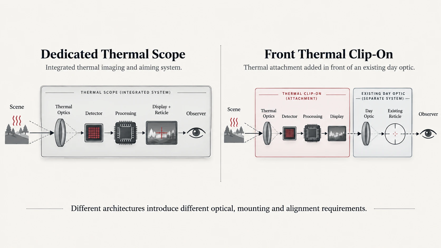
    A dedicated thermal scope is a complete thermal aiming device. Its detector, thermal lens, display, reticle, zeroing system, controls, and mounting interface are designed as one unit.

    A front-mounted thermal clip-on takes another approach. It adds thermal imaging in front of an existing day optic, allowing the user to continue looking through the familiar daytime riflescope.

    That can make a clip-on highly versatile, but it also introduces extra variables: adapter fit, optical alignment, day-scope magnification, balance, display positioning, and repeatability when the attachment is removed and installed again.

    So the useful question is not:

    Which system is universally better?

    It is:

    Which architecture better fits the existing optic, intended use, mounting system, and thermal workflow?

    For a broader look at thermal attachments, see our thermal clip-on buyer’s guide.

    What Is a Dedicated Thermal Scope?

    A dedicated thermal scope integrates the complete thermal imaging and aiming chain into one device.

    The system normally includes:

    • thermal detector;
    • thermal objective lens;
    • image processing;
    • internal display;
    • aiming reticle;
    • zeroing system;
    • mounting interface.

    The user observes the thermal image directly through the device.

    The day optic is not part of the imaging chain.

    This allows the manufacturer to design detector resolution, lens focal length, base magnification, field of view, display, reticle, digital zoom, controls, and mounting geometry as one system.

    What Is a Front-Mounted Thermal Clip-On?

    A front-mounted thermal clip-on is designed to sit in front of an existing day optic.

    The attachment first forms a thermal image.

    That image is then viewed through the day scope behind it.

    In a typical front-attachment arrangement:

    the thermal unit supplies the image, while the existing day optic continues to provide the familiar viewing position and reticle.

    This architecture can allow the same day optic to remain part of the setup during both normal and thermal use.

    But that versatility depends heavily on compatibility between:

    • clip-on;
    • adapter;
    • day optic;
    • magnification range;
    • optical axis;
    • mounting system.

    A clip-on should therefore never be selected solely from detector specifications.

    The Two Systems Have Different Optical Chains

    The simplest way to understand the difference is to follow the image path.

    Dedicated Thermal Scope

    Scene
    → Thermal objective
    → Detector
    → Processing
    → Display
    → Eyepiece
    → Observer

    The entire imaging system belongs to the thermal scope.

    Front Thermal Clip-On

    Scene
    → Clip-on thermal objective
    → Detector
    → Processing
    → Clip-on display
    → Day optic
    → Observer

    The day optic now becomes part of the final viewing chain.

    That difference affects magnification, field of view, alignment, image presentation, and mounting.

    Zeroing Works Differently

    A dedicated thermal scope has its own electronic reticle and zeroing system.

    Its point of aim is established within that thermal device.

    A front clip-on usually works differently.

    The day optic already has an established reticle and zero.

    A properly designed clip-on attempts to place the thermal image into that existing optical path without changing the relationship between the day optic’s reticle and the target.

    This is why manufacturers often promote zero retention as a key benefit of front attachments.

    But that claim needs careful wording.

    “No Re-Zero” Is Not a Universal Guarantee

    A clip-on can be engineered so that installation is intended not to require a completely new zero.

    That does not mean point-of-impact shift is physically impossible.

    Practical repeatability depends on factors including:

    • adapter fit;
    • attachment alignment;
    • mount repeatability;
    • day-optic mounting stability;
    • mechanical tolerances;
    • correct installation;
    • display calibration where provided.

    Some clip-on systems explicitly include a display-calibration function for correcting observed point-of-impact shift after installation.

    Therefore the technically accurate wording is:

    A compatible clip-on may be designed to preserve the existing day-optic zero, but installation and repeatability should still be verified according to the manufacturer’s procedure.

    Do not reduce this to:

    “clip-ons never require re-zeroing.”

    Mechanical Alignment and Image Alignment Are Different

    A clip-on system involves at least two related alignment problems.

    Mechanical Alignment

    The attachment must be mounted consistently relative to the day optic.

    That includes:

    • adapter seating;
    • concentricity;
    • rotational position;
    • clamp repeatability;
    • physical stability.

    Image Alignment

    The thermal image must also appear correctly positioned within the day optic’s field of view.

    Some attachment systems provide mechanical or electronic screen-positioning adjustment.

    This does not replace proper mechanical fit.

    Electronic image correction can compensate for some display alignment differences, but it should not be treated as a substitute for a loose, mismatched, or unstable mounting interface.

    For a more detailed setup discussion, see our thermal attachment installation and calibration guide.
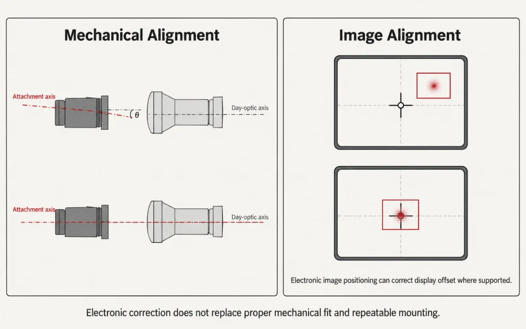
    Diagram comparing mechanical alignment and image alignment in a front-mounted thermal clip-on system

    Day-Optic Magnification Is One of the Biggest Clip-On Variables

    With a dedicated thermal scope, the manufacturer defines the complete magnification system.

    A clip-on is different because the final image is also viewed through the magnification of the day optic.

    At low day-optic magnification, more of the clip-on display may be visible.

    As day-optic magnification increases:

    • the displayed thermal image appears larger;
    • a smaller part of the display may fill the field of view;
    • display pixels can become more apparent;
    • apparent image sharpness may decrease;
    • UI elements may move outside the visible area.

    This is why thermal clip-on manufacturers often specify a recommended day-optic magnification range.

    That range is product-specific.

    It should not be replaced by a generic statement such as:

    “all thermal clip-ons work well up to 10×.”

    Optical Magnification and Display Magnification Are Not the Same Thing

    This distinction is easy to miss.

    A dedicated thermal scope may use:

    • native optical magnification determined by lens and detector geometry;
    • digital zoom applied to the thermal image.

    A front clip-on adds another stage:

    magnification from the day optic behind the clip-on.

    That day optic is not creating new detector information.

    It is enlarging the image presented by the attachment.

    Therefore:

    more day-scope magnification does not create more native thermal detail.

    At some point, the limiting factors become the clip-on detector, processing, display resolution, and optical coupling.

    Field of View Must Be Considered as a System

    Field of view is also more complicated with a clip-on.

    The clip-on has its own thermal field of view.

    The day optic has its own apparent field of view and magnification.

    The usable final view depends on how those two systems interact.

    If the day optic is magnified too far for the attachment:

    • the user may see only the central area of the display;
    • situational awareness can decrease;
    • scanning can become slower.

    This is one reason low-to-moderate day-optic magnification is often important in front-attachment systems.

    The exact usable range remains device-specific.

    Focus Has More Than One Stage in a Clip-On System

    A dedicated thermal scope generally requires the user to manage the thermal device’s focus according to its design.

    A clip-on setup can introduce additional optical variables.

    Depending on the system, the user may need to consider:

    • clip-on objective focus;
    • day-optic focus;
    • day-optic parallax setting;
    • eyepiece / diopter settings.

    These controls do not all solve the same problem.

    A sharp day-optic reticle does not guarantee that the thermal scene itself is correctly focused.

    Likewise, a well-focused thermal image does not automatically mean the day optic is optimally adjusted.

    Balance and Weight Change Differently

    A dedicated thermal scope replaces the conventional day optic in the thermal setup.

    Its mass is concentrated around its own mounting position.

    A front clip-on adds another device in front of an optic that is already installed.

    That can move additional mass forward.

    The result can affect:

    • balance;
    • handling;
    • mounting load;
    • clearance;
    • overall system length.

    This does not mean clip-ons are always heavier.

    A compact attachment may weigh less than a large dedicated thermal scope.

    The point is that weight distribution matters in addition to total weight.

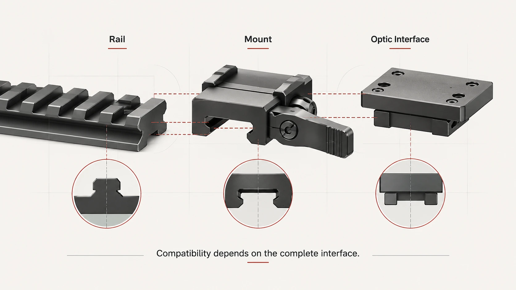
    Mount and Adapter Compatibility Are Critical

    A front attachment must mechanically interface with the host optic or rail system exactly as intended by the manufacturer.

    Depending on the design, compatibility may involve:

    • outer objective housing diameter;
    • dedicated adapter size;
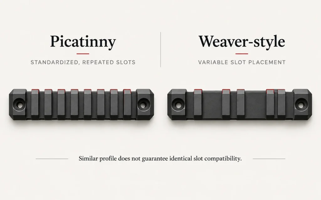
    • rail interface;
    • bayonet interface;
    • insert ring;
    • clamp geometry.

    The nominal objective size printed on the day optic does not necessarily equal the outer diameter required for an adapter.

    For example:

    a “50 mm objective” specification describes optical aperture, not automatically the outside diameter of the objective housing.

    Adapter selection must therefore use the manufacturer’s actual dimensional requirement.

    For more background on interfaces, see thermal-scope mounting standards.

    Removal and Reinstallation Add a Repeatability Requirement

    One of the main attractions of a clip-on is the ability to remove it and return to normal daytime use.

    But once an attachment is designed to come off and go back on, repeatability becomes important.

    A good quick-release or repeatable adapter should return the attachment to a consistent mechanical position.

    Still, repeatability should be verified rather than assumed.

    Factors such as:

    • dirt;
    • incorrect clamping;
    • adapter wear;
    • damaged interfaces;
    • incomplete seating

    can affect how consistently the attachment returns to position.

    A marketing phrase such as:

    “remove and reinstall with zero loss”

    should therefore be treated as a product-specific verified claim—not a generic truth about all thermal clip-ons.

    Does a Clip-On Preserve the Day Optic’s Reticle?

    In typical front-attachment use, yes: the user continues viewing the day optic’s existing reticle.

    That is one of the major architectural differences from a dedicated thermal scope.

    The clip-on’s job is to insert a thermal image into the day optic’s optical path.

    However, this does not mean the attachment is mechanically irrelevant to aiming.

    The thermal image still has to remain properly aligned with the optical system.

    Therefore the correct concept is:

    retained day-optic reticle plus verified attachment alignment.

    Not:

    the attachment can never affect point of impact.

    Does a Dedicated Thermal Scope Have an Alignment Advantage?

    A dedicated thermal scope avoids the additional clip-on/day-optic interface.

    Its detector, display, reticle, and mounting system belong to one integrated device.

    This reduces the number of interfaces involved in the optical chain.

    However, that does not automatically make every dedicated scope more mechanically accurate than every clip-on.

    Dedicated systems still depend on:

    • mount quality;
    • zeroing;
    • reticle calibration;
    • mechanical stability;
    • recoil qualification;
    • correct installation.

    The architecture is simpler, but product quality still matters.

    Detector Resolution Does Not Decide the Comparison by Itself

    It is tempting to compare:

    dedicated thermal scope detector resolution

    against:

    clip-on detector resolution

    and choose the larger number.

    That is incomplete.

    For either architecture, image usability also depends on:

    • detector resolution;
    • pixel pitch;
    • NETD;
    • lens;
    • field of view;
    • focus;
    • processing;
    • display.

    For a clip-on, the day optic adds another major variable.

    A high-resolution thermal detector viewed through excessive day-scope magnification can still produce a disappointing final image.

    NETD Matters to Both Thermal Architectures

    NETD describes thermal sensitivity under specified test conditions.

    The principle applies whether the detector sits inside:

    • a dedicated thermal scope;
    • a thermal front attachment.

    Lower NETD can help separate smaller thermal differences when other conditions are comparable.

    But NETD does not determine:

    • zero retention;
    • mount repeatability;
    • adapter compatibility;
    • day-optic magnification;
    • balance.

    Thermal sensitivity and platform integration are separate questions.

    Weather Affects Both

    Both dedicated thermal scopes and thermal clip-ons depend on thermal infrared information traveling through the atmosphere.

    Fog, rain, humidity, and long atmospheric paths can reduce usable thermal contrast.

    A clip-on does not see through weather simply because it sits in front of a day optic.

    Likewise, a dedicated thermal scope does not eliminate atmospheric attenuation.

    Environmental sealing also remains product-specific.

    IP67 on one device does not mean every device in the category has IP67 protection.

    Weather claims must therefore stay tied to the exact model.

    Day-to-Night Flexibility Is Where Clip-Ons Are Most Distinctive

    A front attachment can preserve an existing day optic as part of the overall setup.

    During daylight, the attachment can be removed and the day optic used normally.

    When thermal capability is needed, the attachment can be installed again if the system is designed for repeatable mounting.

    This architecture can reduce the need to replace the complete sighting system.

    That is the core versatility advantage of a clip-on.

    But it comes with additional requirements:

    • adapter compatibility;
    • repeatability;
    • optical alignment;
    • day-scope magnification compatibility.

    A Dedicated Thermal Scope Is More Self-Contained

    A dedicated thermal scope does not rely on a separate day optic for the final image.

    That can make the overall thermal configuration more straightforward.

    The user evaluates one integrated system for:

    • base magnification;
    • field of view;
    • display;
    • reticle;
    • zeroing;
    • power;
    • controls;
    • mounting.

    This can be attractive when thermal imaging is the primary observation mode rather than an occasional addition to a daytime optic.

    For more on evaluating a complete dedicated setup, see how to match a thermal scope to your rifle.

    Thermal Scope vs. Clip-On: Practical Comparison

    QuestionDedicated Thermal ScopeFront Thermal Clip-On
    Complete thermal aiming systemYesWorks with an existing day optic
    Uses day-optic reticleNoTypically yes
    Has its own zeroing systemYesAlignment/calibration varies by design
    Existing day optic remains installedNot part of thermal chainYes
    Day-optic magnification affects thermal imageNoYes
    Additional adapter requiredScope mount onlyUsually yes
    Optical-axis alignment between two devicesNot applicable in same wayImportant
    Remove for normal daytime useRequires optic/system changeCore advantage
    Weight distributionIntegrated unitAdditional forward-mounted mass
    Zero retention after reinstallationScope/mount dependentAdapter and attachment dependent
    Detector/NETD importanceYesYes
    Weather effectsProduct/environment dependentProduct/environment dependent
    Best use caseDedicated thermal-first setupDay-optic-first flexible setup

    Neither column is a universal winner.

    The table describes system architecture.

    When a Dedicated Thermal Scope Usually Makes More Sense

    A dedicated thermal scope may be the better fit when:

    • thermal imaging is the primary viewing mode;
    • you want one integrated thermal aiming system;
    • you prefer the manufacturer’s own thermal magnification and reticle workflow;
    • you do not need to preserve an existing day optic in the same optical chain;
    • reducing adapter and alignment interfaces is important.

    The exact product still needs to be selected by detector, optics, field of view, mounting, power, and verified mechanical specifications.

    When a Thermal Clip-On Usually Makes More Sense

    A front clip-on may be the better fit when:

    • you already have a day optic you want to retain;
    • daytime and thermal use need to alternate;
    • the host optic falls within the attachment’s supported magnification range;
    • the correct adapter is available;
    • repeatable removal and reinstallation are important;
    • the combined weight and balance remain acceptable.

    A clip-on is not automatically the better choice simply because it is more modular.

    Compatibility determines whether that modularity is useful.

    Current Yubeen Products Should Be Represented Accurately

    Yubeen’s current confirmed thermal range includes dedicated thermal imaging products.
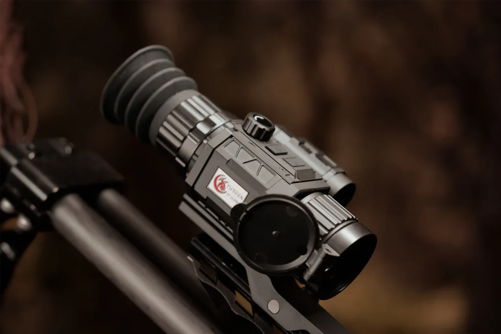
    Confirm the exact model, integrated LRF, supported ballistic functions, required data sources, orientation sensors, display behavior, software version, profile support, app requirements, documentation, warranty, and technical support.
    Current Yubeen Products Should Be Represented Accurately

    The current product material available for this audit does not establish a current Yubeen thermal clip-on model that should be promoted as an active product in this article.

    Therefore this article should not:

    • generate a fake Yubeen clip-on;
    • relabel another device as a clip-on;
    • reuse an obsolete model as though it were current.

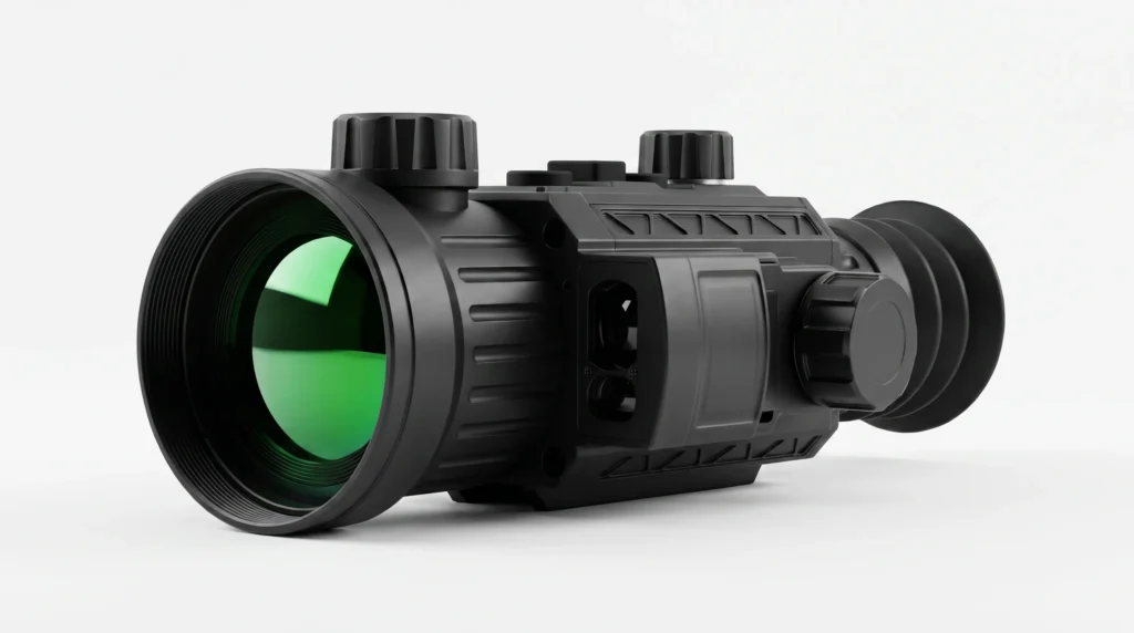
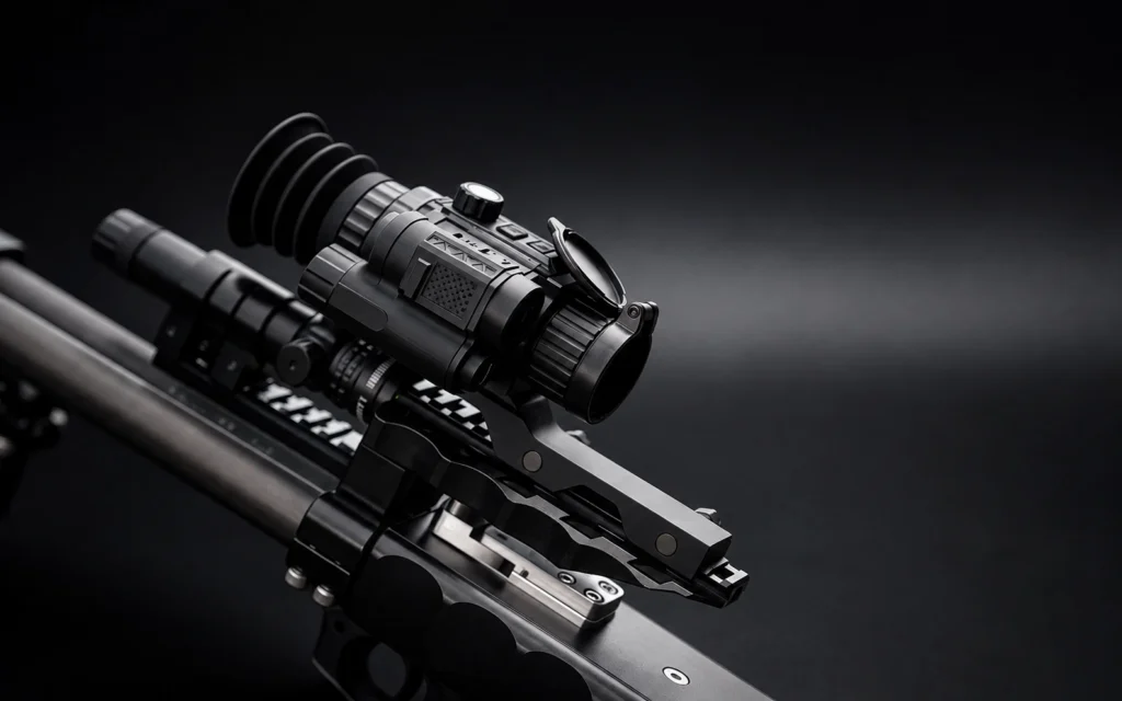
    The Yubeen product image in this article should represent the dedicated thermal-scope side of the comparison.

    For current product information, review the current Yubeen thermal imaging range.

    How to Choose Between a Dedicated Scope and a Clip-On

    Before choosing either architecture, compare:

    1. whether thermal imaging or daytime optics will be the primary viewing mode;
    2. whether an existing day optic must remain in use;
    3. supported day-optic magnification range;
    4. adapter and objective-housing compatibility;
    5. mechanical repeatability after removal and reinstallation;
    6. detector resolution and NETD;
    7. lens and field of view;
    8. total system weight and balance;
    9. mounting and recoil requirements;
    10. weather protection and environmental specifications for the exact product.

    If using a clip-on, add one more requirement:

    verify installation, alignment, and point-of-impact behavior according to the exact manufacturer’s procedure.

    The Better Setup Depends on the Optical System Around It

    A dedicated thermal scope and a front clip-on solve different integration problems.

    The dedicated scope builds thermal imaging, display, reticle, zeroing, and mounting into one system.

    The clip-on preserves an existing day optic and adds thermal capability in front of it.

    That versatility is real—but so are the extra variables introduced by the adapter, optical alignment, magnification, balance, and repeatability.

    The best choice is therefore not decided by detector resolution alone.

    It is decided by the complete optical and mechanical system.

    FAQ

    Does a Thermal Clip-On Always Keep the Existing Zero?

    No. Compatible clip-ons may be designed to preserve the day optic’s zero, but mounting, alignment, repeatability, and calibration still matter. Follow the procedure for the exact attachment and verify performance after installation.

    Does a Clip-On Need Its Own Reticle?

    In typical front-mounted use, the existing day optic reticle remains the main aiming reference. The exact display and calibration system varies by attachment.

    Can I Use Any Magnification With a Thermal Clip-On?

    No universal magnification range applies to every attachment. Manufacturers commonly specify a recommended host-optic magnification range because increasing day-scope magnification also enlarges the clip-on display image.

    Does More Day-Scope Magnification Create More Thermal Detail?

    No. The day optic can enlarge the displayed thermal image, but it does not create additional native detector information.

    Is a Dedicated Thermal Scope More Accurate Than a Clip-On?

    Not automatically. Accuracy and repeatability depend on the complete system, including mounting, zeroing, mechanical stability, optics, alignment, and product quality.

    Is a Clip-On Better for Day-to-Night Use?

    It can be more convenient when the goal is to retain an existing day optic and add thermal capability when needed. The benefit depends on adapter compatibility, repeatability, balance, and magnification compatibility.

    Do Dedicated Thermal Scopes and Clip-Ons Perform the Same in Bad Weather?

    Both depend on thermal infrared transmission through the atmosphere. Fog, rain, humidity, and distance can affect both, while enclosure protection remains product-specific.
  • Thermal Imaging for Predator Control and Pest Management: Capabilities and Limits

    Thermal Imaging for Predator Control and Pest Management: Capabilities and Limits

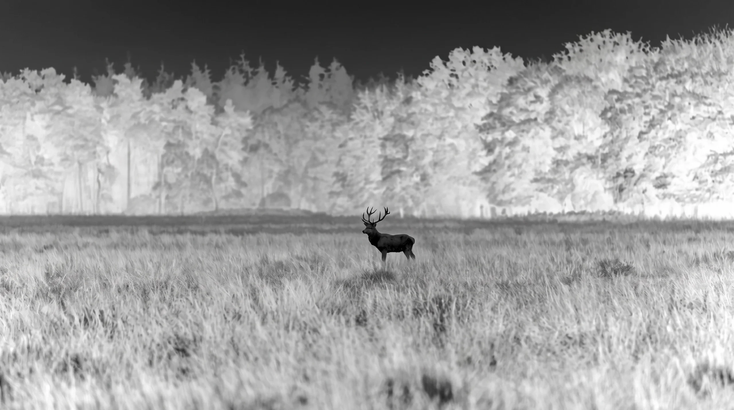
    Thermal imaging for predator control can make thermally distinct animals easier to locate in low light, but detection is not the same as identification.

    That can make a thermally distinct animal easier to locate in darkness, low light, or visually cluttered environments.

    But thermal imaging should not be treated as automatic identification technology.

    A visible heat signature may be enough to detect that an animal is present while still providing too little information to determine species, size, orientation, or surrounding conditions with confidence.

    The practical value of a thermal scope therefore depends on more than detector specifications.

    It depends on:

    • target-to-background thermal contrast;
    • distance;
    • detector resolution;
    • lens and field of view;
    • focus;
    • atmosphere;
    • vegetation;
    • terrain;
    • image processing;
    • the user’s ability to interpret the scene.

    For the underlying imaging principle, see what thermal imaging can reveal beyond the human eye.

    Why Thermal Imaging Can Help in Low-Light Field Work

    Visible-light observation depends on reflected light.

    As illumination falls, visual contrast can disappear.

    A dark animal against dark vegetation may become difficult to separate using unaided vision even when the animal remains physically present.

    Thermal imaging approaches the scene differently.

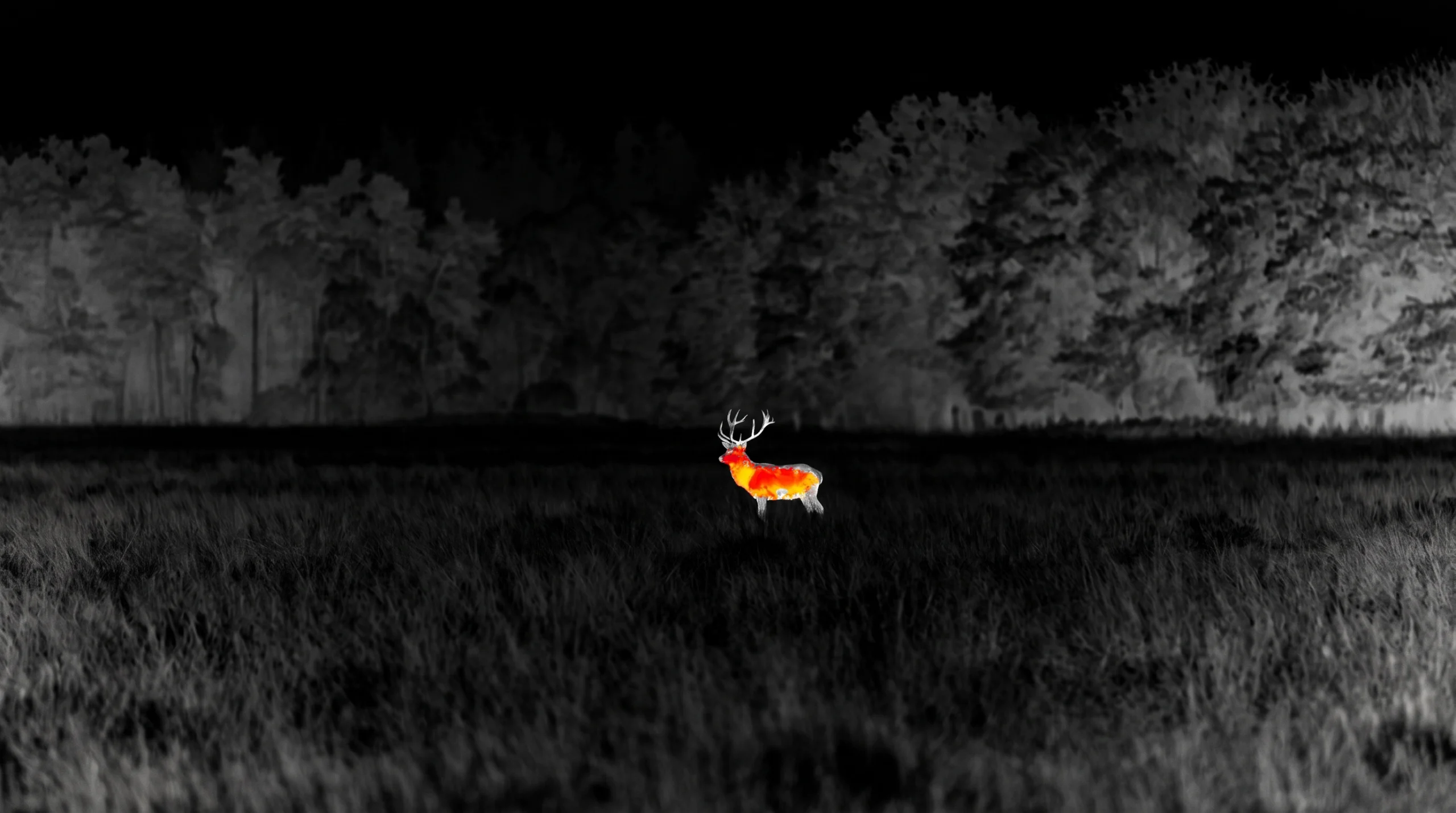
    If the animal produces a sufficiently different infrared signal from the background, the detector may render that difference clearly even when visible illumination is extremely low.

    This can make thermal imaging particularly useful for:

    • locating movement at field edges;
    • scanning open ground;
    • observing around livestock areas;
    • checking likely travel routes;
    • searching terrain after sunset.

    The important condition is:

    sufficient thermal contrast must reach the detector.

    Darkness alone does not guarantee a strong thermal image.

    Thermal Imaging Does Not Require Visible Darkness

    A thermal detector does not need the scene to be dark.

    It can operate during:

    • daylight;
    • dusk;
    • night;
    • dawn.

    The detector is responding to thermal infrared radiation rather than waiting for the sun to disappear.

    However, the thermal scene changes throughout the day.

    Sunlight heats:

    • soil;
    • rock;
    • buildings;
    • vegetation;
    • equipment;
    • other surfaces

    at different rates.

    Those surfaces also cool at different rates after sunset.

    As a result, target-to-background thermal contrast can be very different at:

    • midday;
    • late afternoon;
    • shortly after sunset;
    • the middle of the night;
    • early morning.

    For more on this difference, see how thermal imaging works during daylight.

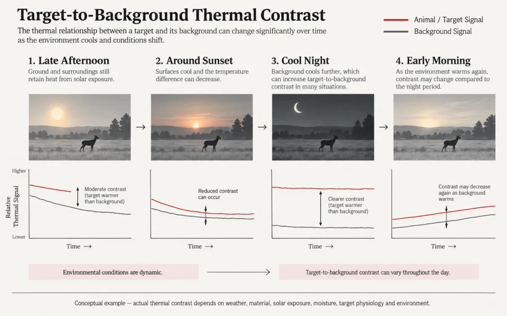
    Thermal Crossover Can Reduce Contrast

    One of the most important field limitations is thermal crossover.

    Thermal crossover occurs when the apparent thermal signal of the target and background move closer together.

    For example, a background that has absorbed solar energy during the day may remain warm after sunset.

    If the surrounding ground, vegetation, structures, and target produce similar apparent thermal signals, the target may become more difficult to separate.

    Later, as the environment cools, contrast may increase again.

    This is why a thermal image should never be judged only from the time of day.

    Actual scene contrast matters.

    thermal-target-background-contrast-through-time

    Detection Is the First Step, Not the Final Answer

    Thermal imaging is often especially effective at answering:

    Is there a thermally distinct object in this area?

    That is a detection task.

    At longer distances, however, an animal may occupy only a small number of detector samples.

    The image may reveal:

    • presence;
    • movement;
    • approximate location;
    • broad size.

    It may not reveal enough information to confirm exactly what the animal is.

    Recognition Requires More Spatial Information

    Recognition becomes possible when the image contains enough information to classify the subject more broadly.

    Useful cues may include:

    • overall shape;
    • relative size;
    • posture;
    • movement pattern;
    • visible body proportions.

    But those cues can still be ambiguous.

    Animals with similar body size or geometry may produce similar low-detail thermal silhouettes.

    Identification Is More Demanding Again

    Identification requires enough reliable information for the exact distinction that matters operationally.

    That threshold is task-dependent.

    A heat source that is obvious enough to detect at one distance may still be unsuitable for confident species identification.

    For that reason:

    a quoted detection range should never be treated as an identification range.

    For the complete explanation, see our guide to thermal detection, recognition and identification.

    Small Animals Are Especially Demanding

    Small pests can be difficult thermal targets for a simple reason:

    they occupy fewer detector samples at a given distance.

    This means image detail can disappear quickly as distance increases.

    The result depends on:

    • animal size;
    • orientation;
    • detector resolution;
    • pixel pitch;
    • lens focal length;
    • field of view;
    • focus;
    • thermal contrast.

    A smaller subject does not automatically disappear thermally.

    But it generally requires more favorable distance and imaging conditions to provide useful spatial detail.

    Vegetation Can Hide Thermal Targets

    Thermal imaging does not make vegetation transparent.

    A warm animal may remain partly visible through gaps in:

    • grass;
    • branches;
    • sparse brush.

    That is line-of-sight visibility through gaps.

    It is not penetration through vegetation.

    Dense:

    • leaves;
    • brush;
    • tree trunks;
    • crops;
    • terrain

    can partially or completely block the direct thermal signal.

    Scientific wildlife studies similarly identify vegetation density and canopy cover as important limits on thermal detection and species identification.

    Terrain Can Hide a Target Completely

    The detector only receives radiation from surfaces within its line of sight.

    An animal behind:

    • a ridge;
    • earth bank;
    • large rock;
    • building;
    • dense solid barrier

    cannot simply be reconstructed by thermal imaging.

    This sounds obvious, but it matters in real scanning.

    A wide field of view can help search efficiently, while different observation positions may reveal areas hidden from the original line of sight.

    Weather Changes Useful Range

    Thermal infrared radiation must travel through the atmosphere before reaching the detector.

    Atmospheric conditions can therefore reduce usable contrast.

    Relevant factors include:

    • humidity;
    • fog;
    • rain;
    • distance;
    • temperature difference;
    • aerosol conditions.

    Light fog may still permit useful thermal observation in conditions where visible contrast is poor.

    Dense fog or heavy rain can significantly reduce thermal range.

    The technically accurate statement is:

    thermal imaging may retain an advantage over visible observation in some poor-visibility conditions, but it does not eliminate atmospheric attenuation.

    For the detailed explanation, see how weather affects thermal imaging.

    Detector Resolution Matters, but It Does Not Work Alone

    Detector resolution determines how many native thermal samples are available.

    More detector samples can provide more spatial information when other variables are comparable.

    But resolution alone does not determine field performance.

    A higher-resolution detector cannot compensate completely for:

    • weak thermal contrast;
    • poor focus;
    • excessive distance;
    • unsuitable lens choice;
    • dense vegetation;
    • atmospheric attenuation.

    Detector resolution should therefore be evaluated as part of the complete imaging system.

    NETD Matters When Thermal Differences Become Small

    NETD is a measure of thermal sensitivity under specified test conditions.

    When target-to-background contrast is strong, small sensitivity differences may be less important.

    When thermal signals move closer together, system noise becomes more significant.

    Lower NETD can help preserve smaller thermal differences under comparable conditions.

    But NETD does not determine:

    • target size;
    • spatial resolution;
    • identification distance;
    • field of view;
    • line-of-sight obstruction.

    It is one part of the system.

    Lens and Field of View Change the Scanning Workflow

    Lens focal length and detector size determine angular field of view.

    A wider field of view can make it easier to scan:

    • larger fields;
    • tree lines;
    • livestock areas;
    • nearby terrain.

    A narrower field of view can place more of the available detector sampling across a smaller angular scene.

    That can help distant subjects occupy more of the image.

    But the trade-off is reduced scene coverage.

    This creates a practical choice:

    wider FOV for searching

    versus:

    narrower FOV for more distant detail.

    There is no universal best focal length for predator or pest work.

    Digital Zoom Does Not Create New Detector Information

    Digital zoom enlarges data already recorded by the detector.

    It can make a subject easier to inspect on the display.

    It does not add new native detector samples.

    If an animal occupies only a few native pixels, enlarging the display cannot recover information that was never captured.

    Processing and super-resolution may improve image presentation on products that support those functions.

    They should still be distinguished from native detector resolution.

    Laser Rangefinding Can Add Useful Distance Information

    Some thermal products integrate a laser rangefinder.

    Where present, an LRF can provide distance information that is difficult to estimate visually from a thermal image alone.

    That can be useful because thermal scenes may contain fewer familiar visual distance cues than daytime optical images.

    But an LRF does not improve species identification.

    It answers:

    How far away is the measured point?

    It does not answer:

    What exactly is the thermal subject?

    LRF implementation, range capability, measurement behavior and integration are product-specific.

    For a broader comparison, see LRF vs. non-LRF thermal scopes.

    Ballistic Functions Are Separate From Thermal Detection

    Some thermal platforms may include ballistic-related software.

    Those functions should not be confused with thermal image performance.

    A ballistic tool may use inputs such as:

    • measured range;
    • projectile data;
    • zero information;
    • environmental assumptions.

    It does not improve:

    • detector resolution;
    • NETD;
    • focus;
    • thermal contrast;
    • species identification.

    Ballistic functions should therefore be treated as workflow features, not as thermal-imaging capability.

    They must also be verified for the exact product.

    Recording Can Support Documentation

    Some thermal devices provide:

    • still-image capture;
    • video recording;
    • internal storage.

    Where available, recording can help document:

    • observed animal activity;
    • location patterns;
    • repeated visits;
    • equipment evaluation;
    • field conditions.

    Recording can be useful in pest-management workflows where observations need to be reviewed later.

    But it should not be described as a universal thermal-scope feature.

    Storage capacity and recording functions vary by model.

    Thermal Imaging Can Help Separate Search From Confirmation

    A useful field workflow separates several tasks.

    Locate

    Use the thermal image to search for anomalous thermal signatures.

    Assess

    Observe:

    • movement;
    • size;
    • location;
    • surrounding terrain;
    • thermal contrast.

    Confirm

    Do not rely on a vague heat source alone when species identification matters.

    Obtain enough information to confirm:

    • species;
    • position;
    • relevant surroundings;
    • whether the situation meets local requirements.

    Measure Where Supported

    If the device includes an LRF, distance information can be added to the assessment.

    Record Where Supported

    If recording is available, observations can be documented for later review.

    This workflow is more defensible than treating the first visible thermal signal as a complete answer.

    Farm and Livestock Environments Create Thermal Clutter

    Agricultural environments often contain many objects with strong thermal signatures.

    Examples can include:

    • animals;
    • buildings;
    • machinery;
    • stored materials;
    • sun-heated ground;
    • water systems;
    • vehicles.

    This can create thermal clutter.

    A bright or warm signature is not automatically the intended subject.

    Scene knowledge remains important.

    Rocks and Structures Can Produce False Visual Cues

    Inanimate objects can remain warm after absorbing solar energy.

    A rock, wall, roof, equipment housing or patch of ground may appear thermally prominent.

    At long distance or low spatial resolution, such objects can initially resemble an animal-sized thermal anomaly.

    Movement and additional spatial information can help interpretation.

    This is another reason detection should not be equated with identification.

    Predator and Pest Activity Is Not the Only Variable

    Animal behavior changes with:

    • season;
    • food availability;
    • weather;
    • disturbance;
    • time of day;
    • habitat;
    • local management.

    Thermal imaging can help observe what is present within the device’s limits.

    It cannot guarantee that a particular species will appear in a particular area or on a particular schedule.

    This article therefore avoids success-rate or return-on-investment promises.

    Thermal Imaging Does Not Automatically Reduce Costs

    Thermal equipment can improve observation efficiency in suitable conditions.

    But whether that produces an economic benefit depends on factors such as:

    • operation size;
    • labor;
    • frequency of use;
    • target species;
    • local environment;
    • equipment cost;
    • management objectives.

    Without real operational data, statements such as:

    “thermal pays for itself”

    or:

    “thermal cuts management cost by X%”

    are not technically justified.

    Battery Runtime Becomes a Field Constraint

    Long observation sessions make power management important.

    Actual runtime can vary with:

    • battery capacity;
    • display brightness;
    • recording;
    • wireless functions;
    • LRF use;
    • ambient temperature;
    • processing load.

    Published runtime should therefore be tied to the exact product and stated test conditions.

    A general article should not transfer one model’s runtime to the entire thermal category.

    Environmental Protection Is Product-Specific

    Field equipment may encounter:

    • rain;
    • dust;
    • mud;
    • temperature changes;
    • condensation.

    But enclosure protection varies by model.

    A current product with an IP rating can be described by that verified rating.

    The entire category should not be described as:

    waterproof
    weatherproof
    all-weather

    without qualification.

    Legal and Operational Requirements Vary

    Predator control, pest management, nighttime observation and thermal equipment use are regulated differently across jurisdictions.

    Rules can depend on:

    • species;
    • location;
    • season;
    • land ownership;
    • time of day;
    • equipment type;
    • method of control.

    A thermal device being technically capable of nighttime observation does not mean a particular use is legally permitted everywhere.

    Always confirm current local regulations and land-use requirements before field use.

    Thermal Imaging for Predator and Pest Management: Practical Comparison

    FactorWhat Thermal Imaging Can Help WithImportant Limitation
    DarknessDetect thermal contrast without visible illuminationContrast still depends on scene
    DetectionLocate thermally distinct animalsDetection ≠ identification
    Small pestsReveal thermal signal at suitable distanceFewer pixels on small targets
    VegetationMay reveal exposed parts through gapsCannot see through dense cover
    DaylightCan continue operatingSolar heating changes contrast
    WeatherMay outperform visible imaging in some conditionsFog, rain and humidity reduce range
    Long distanceThermal signatures may remain detectableSpatial detail decreases with distance
    LRFCan add distance data if equippedDoes not identify species
    Ballistic softwareCan support workflow if equippedDoes not improve thermal image
    RecordingCan document observations if equippedProduct-specific
    Field endurancePortable observation capabilityBattery/runtime matter
    Economic benefitMay improve workflow in suitable casesROI requires real operating data

    The purpose of this table is to show where thermal imaging contributes information—and where it does not replace field judgment.

    When Thermal Imaging Is Especially Useful

    Thermal imaging may be particularly useful when:

    • observation occurs after sunset;
    • visible contrast is weak;
    • the search area is open enough to preserve line of sight;
    • a warm-bodied animal is likely to differ thermally from the background;
    • rapid scanning matters;
    • active visible illumination is undesirable;
    • repeated observation of animal activity is useful.

    The actual value still depends on the exact environment and product.

    When Thermal Imaging Becomes More Difficult

    Performance can become more challenging when:

    • vegetation is dense;
    • targets are very small;
    • distance is large;
    • target and background temperatures converge;
    • terrain blocks line of sight;
    • heavy fog or rain is present;
    • the thermal scene contains many warm structures or objects.

    These conditions do not necessarily make thermal imaging useless.

    They reduce the amount or reliability of information available.

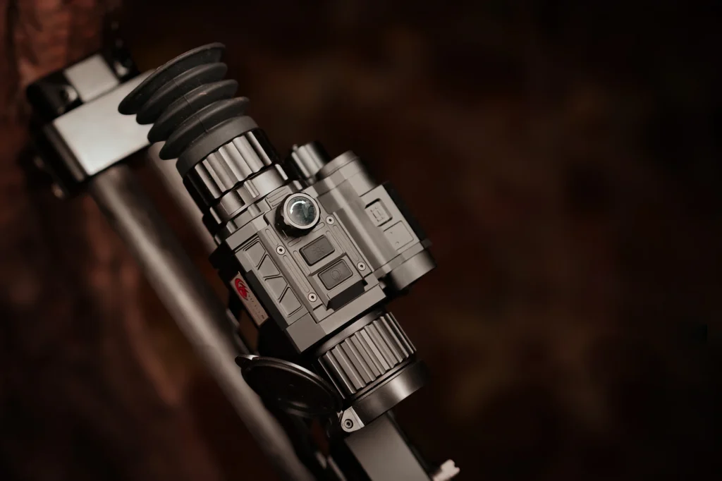
    A Current Yubeen Thermal Product Should Be Judged by the Complete System

    Yubeen’s current thermal products combine detector, thermal optics, image processing, display, controls, power and mechanical hardware.

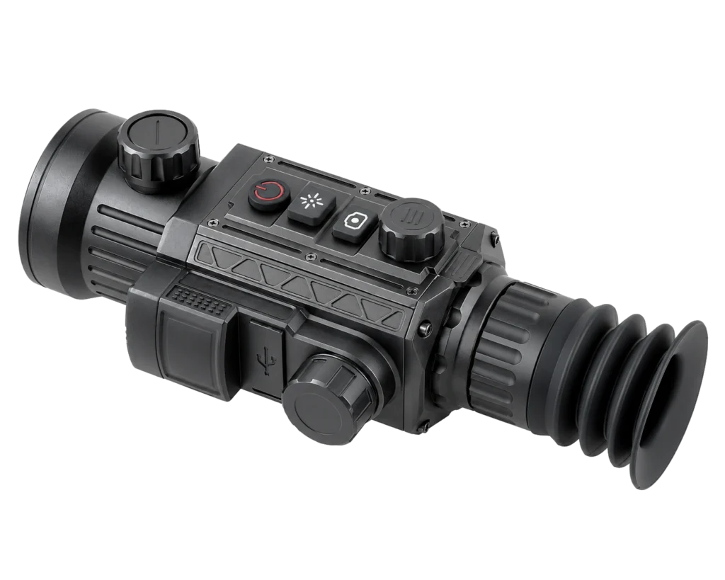
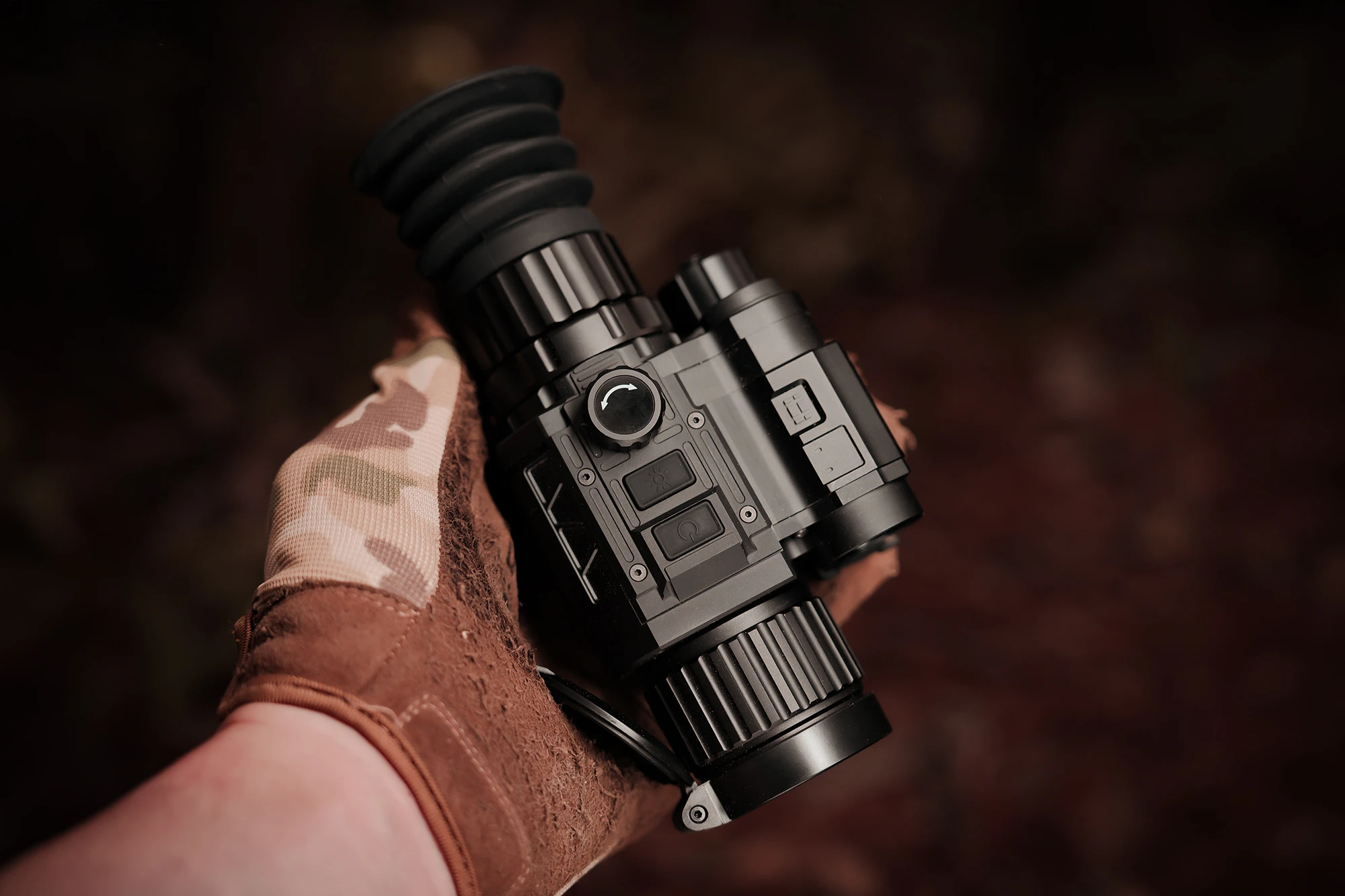
    Yubeen thermal imaging scope illustrating thermal image processing technology
    A current Yubeen thermal imaging product. Exact detector, optics, ranging, recording and environmental specifications vary by model.

    The exact capabilities must be taken from the current documentation for the specific model.

    Do not transfer:

    • detector resolution;
    • NETD;
    • lens;
    • LRF capability;
    • recording;
    • ballistic functions;
    • runtime;
    • IP rating;
    • operating temperature

    from one Yubeen model to another.

    The article’s role is to explain how thermal imaging supports the application—not to turn one model into a universal representation of every thermal product.

    You can review the current Yubeen thermal imaging range after identifying the field of view, distance, sensitivity and integration requirements that matter for the application.

    How to Evaluate a Thermal Scope for Predator or Pest Work

    Use the following checklist:

    1. What size of animal needs to be detected?
    2. At what realistic distance?
    3. Is detection enough, or is confident identification required?
    4. How dense is the vegetation?
    5. How wide an area needs to be scanned?
    6. What field of view is appropriate?
    7. What detector resolution and NETD are available?
    8. Is integrated ranging required?
    9. Is recording required?
    10. What runtime is realistic for the field session?
    11. What weather protection does the exact model provide?
    12. What local regulations govern the intended use?

    That is a more reliable selection method than choosing from a headline detection-range number.

    Thermal Imaging Is a Tool, Not an Automatic Outcome

    Thermal technology can make animals easier to locate when their infrared signal separates from the surrounding environment.

    That is a meaningful advantage in many low-light and nighttime situations.

    But the system remains limited by:

    • thermal contrast;
    • detector sampling;
    • optics;
    • atmosphere;
    • vegetation;
    • distance;
    • line of sight.

    And most importantly:

    seeing a thermal signature is not the same as knowing exactly what produced it.

    A technically sound predator- or pest-management workflow therefore uses thermal imaging as an information tool—supported by proper identification, realistic range expectations, product-specific features and local operating requirements.

    FAQ

    Can Thermal Scopes Detect Animals in Complete Darkness?

    Yes, provided sufficient thermal contrast reaches the detector. Thermal imaging does not require visible illumination to form its image.

    Can Thermal Imaging Identify an Animal Species Automatically?

    Not necessarily. A thermal signature may support detection before enough spatial information is available for reliable species identification.

    Can Thermal Scopes See Through Grass or Brush?

    Not through solid vegetation. Exposed parts of a subject may be visible through gaps, but dense vegetation can block the direct thermal signal.

    Do Thermal Scopes Work During Daylight?

    Yes. Thermal imaging does not require nighttime conditions, but solar heating and changing background temperatures can significantly alter thermal contrast.

    Does Fog or Rain Affect Thermal Detection?

    Yes. Fog, rain and humidity can attenuate infrared radiation and reduce useful contrast and range.

    Does an Integrated LRF Improve Thermal Image Quality?

    No. An LRF adds distance information where supported. It does not increase detector resolution, NETD or target identification detail.

    Does Digital Zoom Increase Detection or Identification Detail?

    It enlarges existing image data but does not create additional native detector samples.

    Are Ballistic Functions Included in Every Thermal Scope?

    No. Ballistic functions are product-specific and should be verified for the exact model.

    Is Thermal Imaging Always More Effective at Night?

    Not automatically. Nighttime often creates useful thermal contrast, but actual performance depends on background temperature, weather, target size, optics and other conditions.

  • Marine Thermal Imaging: Navigation, Search, Observation, and Environmental Limits

    Marine Thermal Imaging: Navigation, Search, Observation, and Environmental Limits

    Marine thermal imaging can add useful visual information in darkness and low light, but its performance still depends on weather, range, thermal contrast, and the marine environment.

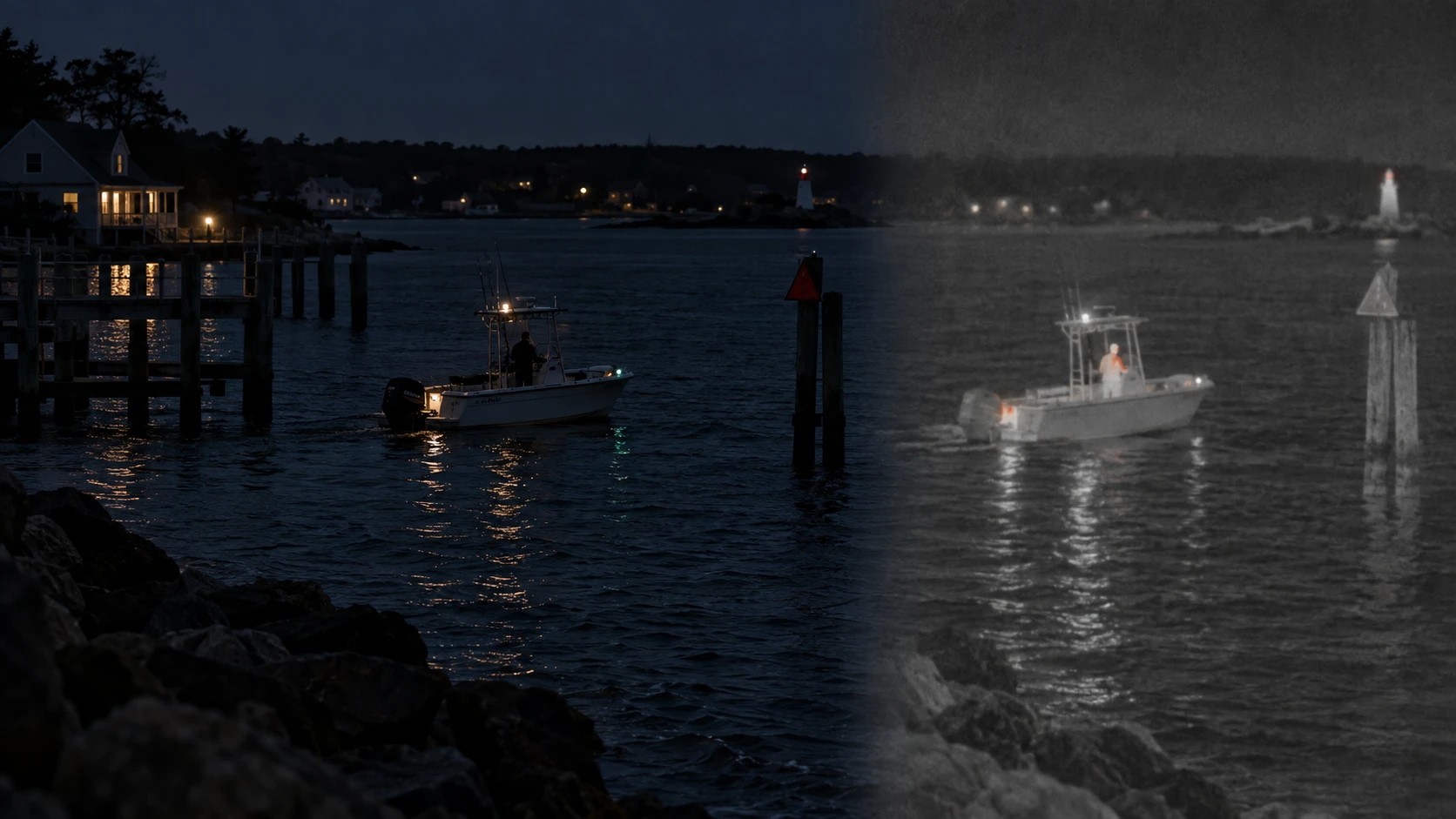
    At night, a thermal imager can reveal temperature differences between vessels, people, shoreline structures, navigation aids, debris, and surrounding water even when the same scene is difficult to interpret with unaided vision.

    But marine use also introduces some of the most demanding conditions for thermal imaging.

    High humidity, fog, rain, sea spray, long atmospheric paths, moving water, small distant targets, and salt contamination can all reduce practical performance.

    Thermal imaging should therefore be treated as an additional source of situational information, not as a replacement for proper lookout, radar, AIS, navigation lights, charts, or other appropriate navigation systems.

    International collision regulations require vessels to maintain a proper lookout and use all available means appropriate to the prevailing conditions.

    The value of thermal imaging is that it can add another visual layer when conventional visible-light observation is limited.

    For the underlying imaging principle, see what thermal imaging can reveal beyond the human eye.

    Why Thermal Imaging Can Be Useful at Sea

    Visible-light observation depends on reflected illumination.

    At night, the sea surface, shoreline, floating objects and distant vessels may have very little visible contrast.

    Thermal imaging operates differently.

    It responds to differences in infrared radiation reaching the detector.

    If an object produces enough thermal contrast relative to the surrounding scene, it may become easier to locate even when visible illumination is extremely low.

    Possible marine uses include:

    • nighttime situational awareness;
    • observing nearby shoreline structures;
    • locating vessels or exposed people;
    • identifying warm machinery or engine areas;
    • checking harbor surroundings;
    • wildlife observation at or above the water surface;
    • supporting search operations.

    The key condition remains:

    useful thermal contrast must reach the detector.

    Darkness alone does not guarantee a useful image.

    Thermal Imaging Is an Aid to Navigation, Not a Navigation Replacement

    A thermal image can help an operator see objects that may be difficult to distinguish visually at night.

    Depending on range and conditions, that can include:

    • pilings;
    • docks;
    • anchored vessels;
    • buoys;
    • floating debris;
    • shoreline features.

    Marine thermal camera manufacturers use thermal imaging for exactly this kind of nighttime awareness.

    But a thermal camera does not provide every type of navigation information.

    It does not replace:

    • radar;
    • AIS;
    • charts;
    • depth information;
    • navigation lights;
    • sound signals;
    • visual and auditory lookout.

    A thermal image is one additional observation channel.

    It should therefore support—not replace—the broader navigation picture.

    Why Darkness Is Not the Only Challenge at Sea

    Marine visibility problems are not limited to a lack of light.

    The atmosphere above water can contain:

    • high humidity;
    • fog;
    • mist;
    • rain;
    • spray;
    • aerosols.

    These conditions affect infrared propagation.

    Even in clear air, some thermal signal is lost along the atmospheric path.

    When humidity, fog or rain increase, usable contrast and range can decrease further.

    Marine aerosols can be particularly demanding for long-distance thermal observation.

    This means:

    thermal imaging may outperform visible observation in some low-light or light-fog conditions,

    but:

    it should not be described as seeing through all fog, rain or sea mist.

    For a deeper explanation, see how weather affects thermal imaging.

    Fog Can Reduce Thermal Range Significantly

    Fog consists of suspended water droplets.

    Those droplets can scatter and absorb part of the infrared signal traveling between the scene and the detector.

    In relatively light fog, thermal contrast may remain useful even when visible contrast is poor.

    As fog becomes denser, the advantage can decrease substantially.

    Under very poor visibility, thermal range can become severely limited.

    The practical result depends on:

    • fog density;
    • wavelength;
    • distance;
    • target size;
    • target-to-background contrast;
    • detector sensitivity;
    • optics.

    There is no single “thermal range in fog” that applies to every system.

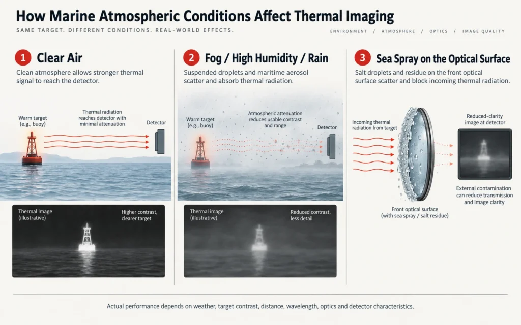
    Rain and Sea Spray Create Different Problems

    Rain affects the thermal path through the atmosphere.

    Sea spray can create another problem closer to the device.

    Water droplets or salt residue on the front optical surface can reduce:

    • contrast;
    • sharpness;
    • transmission.

    A thermal camera with good environmental sealing can still suffer image degradation if the external lens surface becomes coated with water or salt.

    That is an optical contamination problem, not necessarily a detector failure.

    The correct maintenance procedure depends on the exact device and coating.

    Diagram showing how fog humidity rain and sea spray can reduce marine thermal imaging performance

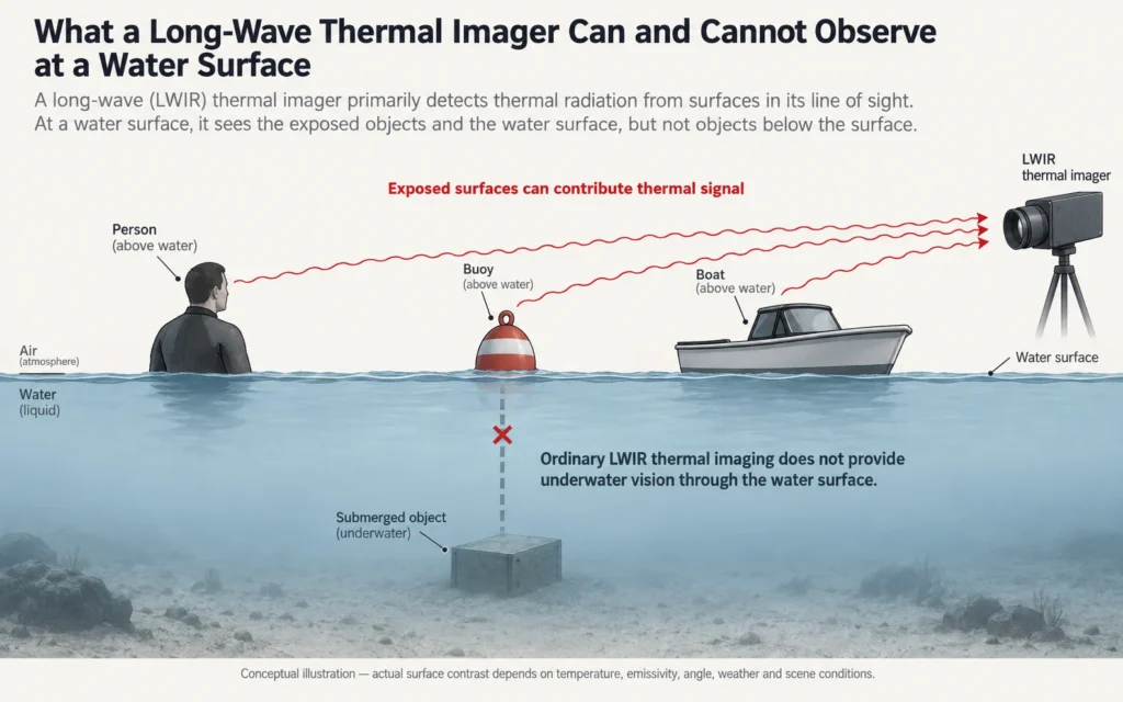
    Thermal Imaging Does Not See Through Water

    One of the most important marine limitations is simple:

    ordinary thermal imaging does not provide underwater vision through the sea surface.

    A thermal detector normally receives infrared radiation from the water surface or from objects exposed above it.

    An object fully submerged below the surface is not imaged as though the water were transparent.

    Thermal imaging can show:

    • a person’s head or body above water;
    • part of an animal exposed at the surface;
    • a floating object;
    • surface-temperature patterns.

    It cannot be relied upon to see:

    • submerged debris;
    • underwater hull structure;
    • a fully submerged person;
    • underwater animals.

    This distinction should remain clear in any marine thermal-imaging claim.

    Diagram showing that thermal imaging can observe exposed surfaces but does not provide underwater vision through water

    Search and Rescue Can Benefit From Thermal Contrast

    Search-and-rescue is one of the strongest marine use cases for thermal imaging.

    A person in the water may be difficult to locate visually at night.

    If part of the body remains exposed above the surface and produces sufficient thermal contrast, a thermal imager may make that exposed area easier to detect.

    Marine thermal systems are widely used to support man-overboard and search operations.

    However, the thermal imager still has limits.

    Detection depends on:

    • how much of the person is visible above water;
    • distance;
    • waves;
    • spray;
    • target contrast;
    • detector resolution;
    • focal length;
    • focus;
    • weather.

    Thermal imaging should therefore be considered a search aid—not a guarantee of detection.

    A Person in the Water Can Be a Very Small Thermal Target

    At longer distance, only a small portion of a person may remain above the waterline.

    That exposed area may occupy only a few detector pixels.

    This creates a familiar thermal-imaging problem:

    detection may occur before recognition or confident identification is possible.

    Higher detector resolution can help preserve more spatial information when other factors are comparable.

    But resolution alone does not eliminate:

    • atmospheric attenuation;
    • wave obstruction;
    • weak contrast;
    • poor focus.

    For the complete framework, see thermal detection, recognition and identification.

    Waves Can Repeatedly Hide a Target

    A marine target is often not continuously visible.

    A person, buoy or small object can disappear behind wave crests and then reappear.

    This means detection can be intermittent even if thermal contrast itself is strong.

    Observation strategy therefore matters.

    A single frame with no visible target does not prove that nothing is present.

    Repeated scanning and multiple information sources remain important.

    Floating Debris Is Not Always Thermally Obvious

    A common assumption is that thermal imaging will make every floating object stand out.

    That is not necessarily true.

    Objects such as:

    • timber;
    • plastic;
    • ropes;
    • buoys;
    • floating debris

    can approach the apparent temperature of the surrounding water.

    When target-to-background thermal contrast is low, the object may become difficult to distinguish.

    Visible-light cameras, radar, spotlighting, or direct visual observation may provide information that thermal imaging does not.

    This is another reason marine thermal should be treated as a complementary sensor.

    Warm Machinery Can Be Easier to Detect

    Vessels and working equipment may contain thermally distinct components such as:

    • engines;
    • exhaust systems;
    • machinery spaces;
    • heated structures.

    These areas may remain visible thermally even when the overall vessel silhouette is difficult to see in darkness.

    But a strong machinery signature does not automatically reveal:

    • vessel identity;
    • vessel heading;
    • operator intent.

    A visible thermal source is only one part of the situational picture.

    Harbor and Coastal Observation

    Thermal imaging can also support general harbor or shoreline observation.

    Depending on conditions, an operator may be able to distinguish:

    • people on docks;
    • vessels moving near shore;
    • warm equipment;
    • shoreline structures;
    • activity around harbor infrastructure.

    The technology can reduce dependence on visible illumination for observation.

    But this article does not treat thermal imaging as an autonomous surveillance or identification system.

    Any identification or operational conclusion requires sufficient information from the complete scene.

    Marine Wildlife Observation

    Thermal imaging can be useful for observing animals that expose part of their body above the surface.

    Examples can include:

    • marine mammals surfacing;
    • birds on the water;
    • shoreline wildlife;
    • animals moving along coastal margins.

    The major limitation remains the same:

    the detector only receives useful thermal radiation from surfaces within its line of sight.

    A fully submerged animal is not visible through the water simply because it is warmer than the surrounding sea.

    Detection Is Not Species Identification

    A thermal signature at the water surface may reveal:

    • movement;
    • approximate size;
    • a warm exposed region.

    That may not be enough to identify the species.

    Distance, viewing angle, partial submersion and wave action can remove important shape information.

    Thermal wildlife observation should therefore separate:

    • detection;
    • recognition;
    • identification.

    The same DRI logic used on land also applies at sea.

    Water Surface Temperature Can Change the Background

    The sea is not a thermally uniform background.

    Surface temperature can vary with:

    • sunlight;
    • currents;
    • wind;
    • freshwater inflow;
    • depth mixing;
    • weather;
    • time of day.

    The apparent thermal contrast between a target and the water can therefore change over time.

    A target that stands out clearly in one set of conditions may become less distinct later.

    This makes the marine environment another example of why thermal performance depends on the scene, not just the device.

    Reflections and Low-Emissivity Surfaces Can Complicate Interpretation

    Not every bright or dark region in a thermal image represents a simple temperature difference.

    Low-emissivity materials can reflect infrared radiation from their surroundings.

    Marine environments contain reflective surfaces such as:

    • polished metal;
    • wet surfaces;
    • certain coated structures.

    This can complicate interpretation.

    Thermal images should therefore be read as infrared radiance patterns rather than simple direct temperature maps.

    Detector Resolution Matters for Small Marine Targets

    A distant buoy, person or small vessel may occupy only a small part of the detector.

    More detector samples across the target can provide more spatial information.

    But detector resolution must be evaluated together with:

    • focal length;
    • field of view;
    • pixel pitch;
    • focus;
    • target size;
    • atmospheric path.

    A higher-resolution detector does not automatically produce a useful long-range image in heavy maritime fog.

    Field of View Determines Search Efficiency

    A wider field of view can make it easier to scan:

    • harbor entrances;
    • nearby water;
    • shoreline;
    • search areas.

    A narrower field of view can make a distant target occupy more of the image.

    This creates the usual trade-off:

    wider FOV → more area visible at one time

    versus:

    narrower FOV → greater target sampling at distance.

    Marine thermal equipment should therefore be selected by realistic observation range and search requirements rather than the largest focal-length number.

    NETD Can Matter in Low-Contrast Marine Scenes

    NETD describes thermal sensitivity under specified test conditions.

    When a target is much warmer or colder than the background, the contrast may already be strong.

    When target and background signals become closer, system noise becomes more important.

    A lower NETD can help preserve smaller thermal differences when other variables are comparable.

    But NETD does not determine:

    • detector resolution;
    • underwater visibility;
    • search area;
    • weather penetration;
    • identification distance.

    It remains one part of the complete system.

    Digital Zoom Does Not Add Native Marine Detail

    Digital zoom enlarges detector information already captured.

    It can help the operator inspect a small region of the display.

    It does not create new thermal samples.

    If a distant target occupies only a few detector pixels, large digital zoom cannot reconstruct detail that was never captured.

    This is particularly important when evaluating small targets on open water.

    Laser Rangefinding Can Be Useful but Is Product-Specific

    Marine environments often provide fewer familiar visual distance cues than land.

    Where a thermal device includes a compatible laser rangefinder, measured distance can add useful information.

    However, LRF performance depends on:

    • target reflectivity;
    • target size;
    • beam placement;
    • geometry;
    • range;
    • atmospheric conditions;
    • exact hardware.

    Open water itself may not provide the same stable ranging surface as a solid target.

    Therefore:

    LRF capability should be checked from the exact product documentation.

    It should not be described as producing guaranteed exact distance to every object on the water.

    Recording Can Support Documentation

    Some thermal imagers provide still-image or video recording.

    Where available, recording can support:

    • incident review;
    • wildlife observation;
    • training;
    • equipment evaluation;
    • documentation of conditions.

    Recording is not universal.

    Storage capacity, frame rate and recording functions remain product-specific.

    Water Resistance and Marine Durability Are Not the Same Thing

    This distinction is critical.

    An IP rating describes specific enclosure tests for ingress protection.

    It does not automatically establish:

    • long-term salt-spray resistance;
    • corrosion resistance;
    • marine certification;
    • suitability for permanent vessel installation.

    Salt water is particularly aggressive toward materials and electrical interfaces.

    A product intended for routine marine use needs its exact environmental specification evaluated—not just the presence of a waterproof rating.

    Salt Spray Can Affect the Optical Surface

    Even when water does not enter the device, salt residue can remain on the external lens.

    That residue can reduce image quality.

    After marine exposure, cleaning should follow the procedure specified for the exact product.

    Do not assume:

    • every thermal device can be rinsed under a tap;
    • every coating tolerates every cleaner;
    • waterproof rating equals unlimited cleaning freedom.

    The external lens and housing still require appropriate care.

    Marine Thermal Imaging Should Complement Radar, AIS, and Lookout

    Thermal imaging provides visual information.

    Radar provides different information.

    AIS provides vessel-transmitted identity and navigation data where available.

    Charts, depth instruments, navigation lights, visual observation and sound provide other information again.

    No single system should be treated as sufficient for every situation.

    A thermal image can help show:

    • what an object looks like thermally;
    • where a thermally distinct feature appears;
    • how activity changes visually.

    It does not replace the navigation picture created from all available information.

    Practical Marine Thermal Imaging Comparison

    Marine TaskWhat Thermal Imaging Can AddImportant Limitation
    Night observationThermal contrast without visible illuminationContrast still depends on scene
    Navigation awarenessVisualize some obstacles and structuresNot a replacement for radar/AIS/lookout
    Person-overboard searchMay reveal exposed body heatWaves, range and weather can hide target
    Small-target detectionCan reveal thermal anomaliesFew detector pixels at distance
    Fog / mistMay outperform visible imaging in some conditionsRange still degrades
    RainCan remain usable in light conditionsHeavy rain reduces contrast/range
    Floating debrisCan reveal some objectsLow-contrast debris may remain difficult
    Wildlife observationCan show exposed animalsCannot see through water
    Machinery observationCan reveal warm componentsDoes not identify vessel or intent
    LRFCan add range where supportedTarget/geometry dependent
    RecordingCan document observationsProduct-specific
    Saltwater usePossible with appropriate equipmentIP rating alone ≠ marine durability

    The point is not that thermal imaging is weak.

    It is that its value depends on how it is integrated with other information.

    When Marine Thermal Imaging Is Especially Useful

    Thermal imaging can be particularly useful when:

    • visible illumination is very low;
    • nearby structures lack clear visual contrast;
    • the goal is to locate warm exposed targets;
    • a shoreline needs observation without additional visible light;
    • search operations continue after dark;
    • an additional visual sensor can complement radar or other systems.

    The exact performance still depends on the thermal system and environment.

    When Thermal Imaging Becomes More Difficult at Sea

    Performance can become more challenging when:

    • fog is dense;
    • rain is heavy;
    • humidity is high;
    • sea spray contaminates the lens;
    • atmospheric distance is long;
    • targets are small;
    • waves repeatedly obscure the target;
    • target and water temperatures become similar.

    These conditions do not necessarily make the thermal imager useless.

    They reduce the amount and reliability of information available.

    Current Yubeen Thermal Products Should Not Be Presented as Marine-Certified Systems Without Evidence

    Yubeen’s current thermal range includes dedicated thermal imaging products.

    Yubeen GX55L thermal imaging riflescope for field use
    A current Yubeen thermal imaging product shown as a general technology example. Marine suitability, ingress protection and salt-exposure capability must be verified for the exact model.

    The product shown here should be treated as an example of Yubeen’s current thermal-imaging technology.

    This article does not classify it as:

    • a marine navigation system;
    • a certified SAR device;
    • a permanent vessel-mounted marine camera;
    • a salt-spray-qualified marine instrument

    unless the exact product documentation establishes those points.

    Model-specific specifications such as:

    • detector resolution;
    • NETD;
    • lens;
    • LRF;
    • recording;
    • runtime;
    • IP rating;
    • operating temperature

    must be checked from the current documentation for that exact model.

    For a broader thermal-selection framework, see how to choose a thermal imaging scope.

    You can also review the current Yubeen thermal imaging range for current product information.

    How to Evaluate Thermal Imaging for Marine Use

    Use this checklist:

    1. What marine task is the system expected to support?
    2. Is it observation, navigation awareness, wildlife viewing, or search?
    3. What target size matters?
    4. At what realistic distance?
    5. What field of view is needed?
    6. What detector resolution and NETD are available?
    7. How often will fog, rain or high humidity be present?
    8. Will salt spray reach the optical surface?
    9. What environmental sealing does the exact model provide?
    10. Is salt-corrosion testing available?
    11. Is the device handheld, fixed-mounted, or another architecture?
    12. Is ranging required?
    13. Is recording required?
    14. What other navigation or observation systems will be used alongside it?

    That evaluation is much more useful than asking whether thermal imaging simply “works at sea.”

    Marine Thermal Imaging Is Valuable Because It Adds Information

    Thermal imaging can add a powerful visual channel to marine observation.

    It can reveal thermal contrast in complete darkness.

    It can help locate exposed people, vessels, shoreline structures and warm equipment.

    It can support search, observation and nighttime situational awareness.

    But it remains subject to:

    • atmospheric attenuation;
    • fog;
    • rain;
    • humidity;
    • spray;
    • range;
    • detector sampling;
    • line of sight;
    • water-surface limitations.

    The correct conclusion is therefore not:

    thermal imaging replaces conventional marine navigation tools.

    It is:

    thermal imaging can add information that visible-light observation may not provide, especially when used alongside other appropriate marine systems.

    FAQ

    Can Thermal Imaging See Through Water?

    No. Ordinary thermal imaging does not provide underwater vision through the water surface. It can show the surface itself and objects exposed above it, but a fully submerged object is generally not visible through the water.

    Can Thermal Imaging Find a Person in the Water at Night?

    It can help when part of the person remains exposed above the surface and produces sufficient thermal contrast. Distance, waves, weather, detector resolution and target exposure still matter.

    Can Thermal Cameras See Through Fog at Sea?

    Not completely. Thermal imaging may retain better contrast than visible imaging in some fog conditions, but fog, humidity and maritime aerosols reduce infrared transmission and useful range.

    Can Thermal Imaging Replace Marine Radar?

    No. Thermal imaging and radar provide different information. Thermal should be treated as an additional visual sensor rather than a replacement for radar, AIS, navigation lights, charts or proper lookout.

    Does an IP67 Rating Mean a Thermal Device Is Marine-Grade?

    No. IP67 describes specific ingress-protection conditions. It does not automatically certify long-term salt-spray or corrosion resistance.

    Can Thermal Imaging Detect Floating Debris?

    Sometimes. Detection depends on object size, distance, temperature contrast, waves, weather and detector/optical performance. Debris close to the water temperature can be difficult to detect thermally.

    Does Thermal Imaging Work During the Day at Sea?

    Yes. Thermal imaging does not require darkness, but solar heating and changing water/structure temperatures can alter target-to-background contrast.

    Does More Detector Resolution Help Marine Search?

    More native detector samples can provide more spatial information when other conditions are comparable, which can help with small distant targets. Atmospheric conditions, lens choice and target contrast still matter.

  • How to Choose a Thermal Scope for Coyote and Hog Hunting

    How to Choose a Thermal Scope for Coyote and Hog Hunting

    Choosing a thermal scope for coyote and hog hunting starts with understanding the environment rather than chasing the largest specification number. Coyotes are often encountered in more open terrain and can move quickly across the field of view, while feral hogs may appear in groups and can be observed across fields, woodland edges, or agricultural land. Those differences affect how much field of view, magnification, image detail, battery life, and ranging capability are useful.

    The best configuration is therefore not automatically the model with the longest stated detection range or highest digital zoom. A useful thermal setup should provide enough field of view to locate and follow an animal, enough native image information to support responsible identification, and a physical configuration that remains practical for the platform and conditions in which it will be used.

    Start With the Environment, Not the Product Name

    Coyote and hog hunting can take place in very different landscapes. A thermal scope that works well across a wide open field may feel unnecessarily narrow in wooded or mixed terrain.

    Before comparing products, define:

    • typical observation distance;
    • terrain type;
    • how often animals are moving;
    • whether multiple animals may be visible at once;
    • typical temperature conditions;
    • how long the equipment normally remains in use.

    These factors determine which thermal specifications deserve the most attention.

    Open Terrain Favors More Image Scale

    Across larger fields or open country, distant subjects occupy fewer detector pixels.

    A narrower field of view and greater base magnification can make a distant subject appear larger in the display, provided the detector and optical system supply enough original image information.

    The trade-off is reduced surrounding context.

    A configuration optimized only for distant viewing can make scanning slower and make it easier to lose a moving subject outside the field of view.

    Mixed or Tighter Terrain Benefits From a Wider Starting View

    Woodland edges, irregular fields, and areas with closer activity can favor a wider starting field of view.

    A wider view makes it easier to scan more of the surrounding area and maintain visual awareness when an animal moves.

    This does not mean lower magnification is always better. It means the starting view should match the distances and movement patterns that occur most often.

    Understand Detection, Recognition, and Identification

    Thermal scope specifications often advertise a single long-distance figure, but useful observation involves different levels of information.

    Detection means noticing that a thermal source is present.

    Recognition means gaining enough information to understand the general type of subject.

    Identification requires enough detail and context to make a responsible determination of what is being observed.

    These distances are not interchangeable.

    A thermal source may be detectable far beyond the distance at which its shape and context can be judged confidently.

    For hunting applications, responsible identification should always take priority over the longest possible detection number.

    Match Field of View and Magnification to the Environment

    Field of view and magnification need to be evaluated together.

    Base Magnification Sets the Starting View

    Base magnification determines how large a subject appears before digital enlargement is applied.

    Higher base magnification can provide more apparent image scale at distance, while lower base magnification normally provides a wider view.

    Neither is automatically better for coyote or hog use.

    A user who regularly scans open fields may value a different starting view from someone working across smaller agricultural fields or mixed woodland.

    Field of View Helps With Scanning and Movement

    Field of view describes how much of the environment is visible at once.

    A wider field can make it easier to locate movement and observe several animals within the same scene.

    A narrower field can devote more of the detector view to a smaller section of the landscape.

    The practical balance depends on actual terrain rather than the animal species alone.

    Digital Zoom Does Not Add Native Thermal Detail

    Digital zoom enlarges the thermal image that has already been captured.

    It can make the displayed subject easier to inspect, but it does not create additional detector pixels.

    For that reason, compare native detector resolution, lens configuration, focus, and starting field of view before comparing maximum digital-zoom numbers.

    If magnification is a major priority, see our thermal scope magnification guide for a more detailed explanation.

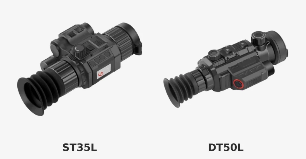
    Yubeen ST35L and DT50L thermal imaging scope comparison

    Sensor Resolution Affects the Detail Available to Work With

    Detector resolution describes how many thermal pixels are used to build the original image.

    A higher-resolution detector can provide more spatial information, which can be useful when viewing smaller subjects or when some digital enlargement is required.

    However, resolution alone does not determine the final image.

    Lens quality, focal length, focus, pixel pitch, NETD, image processing, display quality, environmental conditions, and subject distance all influence the result.

    This is why two scopes with the same detector resolution can still provide different viewing experiences.

    NETD Matters Most When Thermal Contrast Is Limited

    NETD describes thermal sensitivity under defined test conditions.

    Lower NETD can help a thermal system distinguish smaller temperature differences, which becomes more relevant when the subject and background are thermally similar.

    This can occur in humid conditions or during periods when the ground, vegetation, and surrounding environment retain similar temperatures.

    NETD should not be treated as a standalone quality score, however.

    A low NETD value cannot compensate for poor focus, unsuitable field of view, inadequate detector resolution, or an optical configuration that does not match the intended distance.

    For the underlying concept, see our guide to NETD in thermal imaging.

    Weather and Vegetation Still Affect Thermal Performance

    Thermal imaging does not require visible light, but that does not mean environmental conditions become irrelevant.

    Heavy rain, dense fog, high humidity, and similar atmospheric conditions can reduce infrared transmission and lower the thermal contrast available to the system.

    Vegetation is also a physical obstruction.

    A thermal scope may reveal parts of a warm animal through gaps in grass or sparse branches, but it cannot reliably “see through” solid vegetation.

    That distinction is especially important when attempting to identify an animal rather than simply detect a heat source.

    For a deeper explanation, see how thermal imaging scopes work in extreme weather.

    Coyote and Hog Use Can Prioritize Different Viewing Characteristics

    The species label alone should never determine the product, but common observation patterns can change which characteristics are useful.

    Coyote Observation Often Rewards Field Awareness

    Coyotes can move quickly across open or semi-open terrain.

    A practical setup therefore needs enough field of view to acquire and follow movement without forcing the user to operate at excessive magnification.

    Image detail still matters, particularly when distinguishing a coyote from domestic animals or other wildlife.

    A balanced configuration is often more useful than maximizing a single long-range specification.

    Hog Observation May Involve Multiple Animals in One Scene

    Feral hogs are often observed in groups.

    A wide enough field of view can help maintain awareness of the complete scene rather than isolating one thermal shape.

    At the same time, image quality should remain sufficient to evaluate body shape, movement, surroundings, and other contextual information.

    Again, the right specification depends on the actual terrain and distance.

    An Integrated LRF Can Reduce Distance Guesswork

    Judging distance through a digital thermal image can be difficult, particularly at night when familiar visual references are limited.

    An integrated laser rangefinder provides a direct distance measurement on compatible models.

    That can be useful when distance information matters to the observation or decision-making process.

    An LRF should still be evaluated like any other feature:

    • effective ranging conditions;
    • control accessibility;
    • added size and weight;
    • power use;
    • display integration;
    • actual need.

    If distance information is a priority, see our comparison of LRF and non-LRF thermal scopes.

    An LRF does not turn the rest of the setup into an automatic solution. Correct mounting, verified zero, equipment setup, and responsible judgment remain separate requirements.

    Refresh Rate Matters When Subjects Are Moving

    Refresh rate describes how frequently the displayed thermal image is updated.

    A higher refresh rate can make motion appear smoother and can make panning across a scene more comfortable.

    For moving wildlife, this can improve the viewing experience.

    However, refresh rate does not determine image detail by itself.

    Detector resolution, focus, processing, display quality, and field of view still matter.

    A high refresh rate with an unsuitable optical configuration does not automatically produce a better hunting scope.

    Size and Weight Affect Practical Field Use

    Thermal scopes contain more electronics than conventional optical scopes, so size and weight deserve attention.

    Compare the complete installed system:

    • thermal scope;
    • mount;
    • batteries;
    • accessories;
    • external power if used.

    A larger device may provide a different lens or feature set, while a smaller unit may make the system easier to carry and balance.

    The correct choice depends on the platform and how long the equipment is normally carried.

    For a broader compatibility check, see how to match a thermal scope with your rifle.

    Battery Configuration Matters on Longer Sessions

    Runtime figures are useful, but they depend on operating conditions.

    Display brightness, ambient temperature, recording, wireless functions, image processing, and battery condition can all affect real-world operating time.

    Before choosing a model, check:

    • battery type;
    • whether batteries are replaceable;
    • availability of spare cells;
    • external-power support;
    • connector placement;
    • charging requirements.

    A user who expects several hours of continuous observation may value a different power system from someone using the scope intermittently.

    Recording and Connectivity Are Secondary Features

    Recording, image capture, Wi-Fi, app connectivity, and other software features can be useful for documenting observations or reviewing footage later.

    They should not be the first filters.

    Image quality, compatibility, field of view, magnification, durability, and power remain more fundamental.

    Once those requirements are satisfied, recording and connectivity can help distinguish between otherwise suitable models.

    Durability Specifications Need to Match the Real Environment

    Outdoor thermal equipment may encounter moisture, dust, temperature changes, transport vibration, and repeated mounting or handling.

    Look for published environmental and shock specifications for the exact model.

    An IP rating should be interpreted according to its defined test conditions rather than as a promise that the device is unaffected by every type of water exposure.

    Likewise, shock resistance should be checked against the intended platform and mount rather than assumed from marketing language.

    Use a Buyer Checklist Before Comparing Models

    Before selecting a thermal scope for coyote or hog hunting, compare the whole configuration.

    FactorWhat to Check
    TerrainOpen field, mixed terrain, woodland edge or agricultural land
    Typical distanceWhere animals are usually observed, not theoretical maximum
    Base magnificationStarting image scale
    Field of viewAbility to scan and follow movement
    Detector resolutionNative thermal image information
    NETDThermal sensitivity under defined conditions
    LensFocal length, aperture and focus
    Refresh rateSmoothness during motion
    LRFWhether direct distance measurement is useful
    WeightComplete installed system
    PowerBattery type and realistic runtime
    DurabilityEnvironmental and shock specifications
    RecordingWhether documentation is genuinely useful
    SupportCurrent documentation, warranty and service terms

    The correct product is the one that fits the actual environment and workflow—not the model with the largest number in one specification column.

    How to Compare Yubeen Thermal Scope Configurations

    When comparing Yubeen thermal scopes, avoid permanently assigning one model to “coyote hunting” and another to “hog hunting.”

    Instead, use this sequence:

    1. Define typical observation distance.
    2. Decide how much starting field of view is needed.
    3. Compare base magnification.
    4. Compare detector resolution and lens configuration.
    5. Compare NETD and image-processing features.
    6. Decide whether integrated LRF is necessary.
    7. Compare dimensions and installed weight.
    8. Compare battery configuration and runtime.
    9. Confirm current environmental and shock specifications.
    10. Confirm current warranty and technical-support terms.
    Yubeen FX55L thermal imaging scope

    A compact configuration and a larger long-range-oriented configuration can both be appropriate, but for different environments.

    The comparison should remain based on real requirements rather than broad labels such as “coyote model,” “hog model,” or “long-range model.”

    Responsible Identification Comes Before Maximum Range

    Thermal imaging can make warm subjects easier to detect in darkness, but detection alone is not sufficient.

    Users should consider body shape, movement, surroundings, relative size, and other available contextual information before making an identification.

    If the image does not provide enough information, reduce uncertainty rather than treating a distant heat source as confirmed.

    Local hunting rules, permitted species, seasons, equipment restrictions, and night-use regulations can differ by location. Always check the rules that apply where the equipment will be used.

    For a broader land-management perspective, see our guide to thermal imaging for predator control and pest management.

    Final Thoughts

    Choosing a thermal scope for coyote and hog hunting is not about finding one specification that wins every comparison.

    Start with terrain and typical distance. Then balance field of view, base magnification, detector resolution, lens design, NETD, refresh rate, LRF, size, power, and durability.

    Coyotes and hogs may create different observation challenges, but neither species requires a universal “best” scope.

    The most useful configuration is the one that provides enough image information, enough surrounding context, practical handling, and the features that genuinely match the environment in which it will be used.

    FAQ

    Is higher magnification always better for coyote hunting?

    No. Higher magnification provides more apparent image scale, but it also narrows the field of view. A useful configuration needs enough magnification for the expected distance while still allowing the user to scan and follow movement.

    Do I need a 640×512 sensor for hog hunting?

    Not automatically. A 640×512 detector provides more native thermal pixels than a 384×288 detector, but the correct choice also depends on distance, lens design, field of view, focus, thermal sensitivity, size, weight, and budget.

    Does a thermal scope work in complete darkness?

    Yes. Thermal imaging detects infrared radiation rather than relying on visible illumination. However, image quality still depends on thermal contrast, weather, focus, optical design, and environmental conditions.

    Can thermal scopes see through brush?

    Not in the literal sense. Dense vegetation physically blocks infrared radiation. A thermal scope may reveal exposed parts of an animal through gaps or sparse vegetation, but it cannot reliably see through solid cover.

    Is an LRF necessary for coyote or hog hunting?

    No. An integrated LRF can provide useful distance information, but whether it is necessary depends on the distances, environment, and workflow. A non-LRF model can still be appropriate when direct ranging is not a priority.

  • Thermal Clip-On Buyer’s Guide: How to Choose the Right Attachment

    Thermal Clip-On Buyer’s Guide: How to Choose the Right Attachment

    To choose a thermal clip-on well, start with compatibility rather than the largest detection-range or sensor number on the specification sheet. A clip-on has to work as part of an existing optical system, so the daytime scope, adapter, optical alignment, magnification range, mounting arrangement, image quality, size, and power system all matter together.

    The main advantage of a thermal clip-on is flexibility. Instead of replacing the daytime optic, the thermal device adds a thermal image in front of it. That can preserve a familiar daytime setup while adding thermal observation capability when conditions require it. The trade-off is that a clip-on introduces another optical and mechanical interface, which makes compatibility and alignment especially important.

    What Is a Thermal Clip-On?

    A thermal clip-on is a thermal imaging device designed to work with another optic rather than functioning as a complete standalone aiming system. In a typical front-mounted configuration, the attachment sits ahead of the daytime riflescope and presents a thermal image through the existing optic.

    The thermal unit still contains the core components found in other thermal imaging systems: a detector, objective lens, image processor, display, power system, and user controls. The difference is how the image is delivered and how the device integrates with the optic already installed.

    A clip-on therefore should not be evaluated as if it were simply a smaller dedicated thermal scope. The interaction between the thermal device and the daytime optic is part of its performance.

    Check Compatibility With Your Day Optic First

    Compatibility should be the first filter in a thermal clip-on buyer’s guide. A technically capable attachment is not useful if it cannot be mounted correctly or does not work well with the existing optic.

    Confirm the Adapter and Objective Interface

    Check how the clip-on connects to the daytime optic. Some systems attach to a rail, while others use an adapter around the front of the daytime scope.

    If an objective adapter is required, its specified diameter and clamping range must match the actual outside dimensions of the scope—not merely the nominal objective-lens number printed in the model name.

    The adapter should hold the thermal unit securely without interfering with adjustment rings, controls, lens caps, or other equipment.

    Keep the Optical Axes Properly Aligned

    The thermal device and daytime optic need to share a suitable optical alignment.

    Poor alignment can reduce the usable field of view, create uneven image presentation, or require unnecessary correction. Mechanical stiffness also matters because the complete system needs to maintain its relationship after installation and normal use.

    Compatibility is therefore both an optical and a mechanical question.

    Check the Day Scope Magnification Range

    A thermal clip-on image is viewed through the magnification system of the daytime optic. As daytime magnification increases, the user effectively magnifies the displayed thermal image as well.

    That can make a distant subject appear larger, but it also magnifies the display pixels and reduces the visible portion of the thermal image.

    For this reason, maximum daytime magnification should not be considered independently. Check the thermal unit’s recommended magnification range and evaluate image usability at the actual magnifications you expect to use.

    Thermal clip-on mounted in front of a daytime riflescope

    Compare the Thermal Image Before Comparing Extra Features

    After compatibility is confirmed, evaluate the imaging system itself.

    Detector Resolution Determines Native Image Information

    Detector resolution describes how many thermal pixels are available to build the original image.

    A higher-resolution detector can provide more spatial information, but resolution does not work alone. Lens focal length, focus, sensor sensitivity, image processing, display quality, environmental conditions, and subject distance all affect the final view.

    Do not assume that one resolution number automatically determines detection or identification distance.

    Pixel Pitch and NETD Describe Different Things

    Pixel pitch describes the physical spacing of detector pixels. NETD describes thermal sensitivity under defined test conditions.

    Smaller pixel pitch can support more compact optical designs or different combinations of detector size and focal length, but it does not automatically mean better image quality.

    Lower NETD can help preserve thermal contrast when temperature differences are small, but it should not be treated as a standalone image-quality score.

    Compare both values as part of the entire imaging system.

    Lens Focal Length and Field of View Affect How the Clip-On Feels

    Lens focal length strongly influences the starting field of view and apparent image scale.

    A wider field of view is useful when scanning larger areas or following moving subjects. A narrower field of view places more of the available detector area on a smaller scene.

    The correct balance depends on expected distance and terrain.

    For a clip-on, field of view is especially important because the daytime optic will further magnify the displayed thermal image.

    Focus Matters at Real Working Distances

    A thermal image can only make good use of the detector if the optical system is properly focused.

    Check how the device focuses, the practical focus range, and whether the focus control remains easy to reach after installation.

    If possible, evaluate the unit at the distances you actually expect to use rather than judging image quality only from a short indoor demonstration.

    Understand the Relationship Between Clip-On and Daytime Magnification

    Magnification is one of the most commonly misunderstood parts of choosing a thermal clip-on.

    The daytime optic does not add new thermal information. It enlarges the image produced by the thermal attachment.

    At moderate magnification this can make details easier to view. At excessive magnification the thermal display can appear increasingly pixelated or cropped, depending on the clip-on design and the daytime optic.

    The practical question is therefore not:

    “What is the highest magnification of my daytime scope?”

    It is:

    “At which magnification range does this clip-on still provide a useful image through my daytime optic?”

    That range should be tested or confirmed from the product documentation before purchase.

    Evaluate Mounting Stability and Repeatability

    A clip-on is attractive partly because it can be installed and removed when required. That flexibility makes mounting quality especially important.

    Quick-Detach Is Useful Only When the Interface Is Repeatable

    A quick-detach system can make transitions between configurations faster, but convenience alone does not guarantee repeatability.

    The rail, adapter, locking mechanism, installation method, surface condition, and manufacturing tolerances all affect how consistently the unit returns to the same position.

    If repeatability matters, verify it with the exact mount and platform rather than assuming that every quick-detach design behaves identically.

    Do Not Assume “No Re-Zero” Means “No Verification”

    One of the main reasons users choose a clip-on is to retain the daytime optic as the primary aiming reference.

    However, installation still needs to be verified.

    After installing or reinstalling a thermal attachment, confirm that the complete system behaves as expected before relying on it. If the device provides alignment or correction settings, configure them according to the manufacturer’s instructions.

    A clip-on should reduce unnecessary setup changes—not eliminate the need to verify the system.

    Consider Size, Weight, and Balance

    A thermal attachment sits forward of the user and often ahead of the daytime optic. This means even a moderate amount of additional mass can affect balance.

    Compare:

    • device weight;
    • adapter or mount weight;
    • overall length;
    • objective diameter;
    • control accessibility;
    • battery position;
    • available clearance.

    A lighter unit can be valuable for equipment that is carried for long periods, but low weight should not be considered separately from optical performance, durability, and runtime.

    The goal is a configuration that remains practical once the entire assembly is installed.

    Compare Power and Field Runtime

    Runtime figures are useful only when the test conditions are understood.

    Display brightness, wireless functions, recording, ambient temperature, battery condition, processing load, and other settings can affect operating time.

    Check the Battery Type

    Determine whether the clip-on uses:

    • replaceable rechargeable cells;
    • an internal rechargeable battery;
    • a proprietary battery pack;
    • or a combination of internal and external power.

    Replaceable cells can simplify extended field use when spare batteries are available. Internal batteries can reduce external openings and simplify the housing.

    Neither approach is automatically better.

    External Power Can Extend Runtime

    USB or Type-C external power may be useful during extended observation, provided the specific device supports operation while connected.

    Check connector position as well. A cable that is easy to use on a handheld device may become inconvenient after the unit is installed in front of another optic.

    Durability Specifications Need Context

    Thermal equipment used outdoors may encounter rain, dust, low temperatures, heat, vibration, and repeated installation.

    Look for published environmental and shock specifications, but interpret them correctly.

    An IP rating describes defined ingress-protection test conditions; it is not a general statement that a device is unaffected by every type of water exposure.

    Likewise, a shock rating is useful only when the test method and product specification are applicable to the intended setup.

    Do not convert one durability number into a universal compatibility guarantee.

    Decide Which Extra Features Are Actually Useful

    Modern thermal devices can include more than thermal imaging.

    Recording and Image Capture

    Integrated recording can be useful for reviewing observations, documenting field conditions, training, or keeping media without adding another camera.

    If recording matters, check:

    • storage capacity;
    • file transfer method;
    • supported video functions;
    • whether recording affects runtime;
    • and whether storage is internal or removable.

    Wireless Connectivity

    Wi-Fi or app connectivity can make file transfer, configuration, or remote viewing easier on compatible models.

    Before treating wireless control as a purchase priority, check exactly which settings can be controlled through the app and whether the feature is useful for your workflow.

    Image Processing and Display Modes

    Thermal palettes, contrast adjustment, detail enhancement, picture-in-picture, and similar functions can improve usability in different environments.

    They do not replace the underlying detector and optics.

    Evaluate processing features after basic image quality and compatibility have already met your requirements.

    Rangefinding or Ballistic Functions

    Some thermal systems may integrate ranging or ballistic-related tools.

    If those functions are relevant, evaluate exactly how they work, what inputs are required, and whether they remain practical in a front-mounted configuration.

    Do not select a thermal clip-on simply because it has the longest feature list.

    Clip-On or Dedicated Thermal Scope?

    If you have not yet decided between the two formats, the distinction can be summarized simply.

    QuestionThermal Clip-OnDedicated Thermal Scope
    Keep existing daytime optic?Yes, that is the main purposeNo, it replaces the primary optic
    Setup flexibilityHighMore self-contained
    Optical interfacesThermal + day optic + adapter/mountThermal system only
    Daytime optic magnification affects thermal image?YesNo separate day optic
    Installation/alignment sensitivityHigherGenerally simpler system integration
    Best forUsers who want to retain an existing daytime setupUsers who want a dedicated thermal system

    Neither architecture is universally better.

    If you are still deciding between them, read the detailed comparison:

    Thermal Scope vs. Clip-On Attachment: Which Setup Fits Your Rifle?

    That page should handle the format decision; this buyer’s guide assumes you are already seriously considering a clip-on.

    Use This Checklist Before Buying

    Before selecting a thermal clip-on, confirm the following:

    FactorWhat to Confirm
    Day optic compatibilityObjective/adapter size and recommended optic type
    MagnificationUseful magnification range through the clip-on
    AlignmentMounting method and adjustment capability
    DetectorResolution, pixel pitch and thermal sensitivity
    LensFocal length, field of view and focus range
    DisplayResolution, viewing quality and available modes
    MountInterface, repeatability and installation method
    WeightDevice plus adapter/mount
    PowerBattery type, realistic runtime and external-power support
    DurabilityIngress protection, temperature range and shock specification
    ControlsAccessibility after installation
    Extra featuresRecording, connectivity, PIP, ranging or other functions
    SupportDocumentation, warranty terms and technical assistance

    If several of these points are unclear, the product is not yet ready to be compared only by price.

    How to Test a Clip-On Before You Commit

    A real-world evaluation should answer questions a specification sheet cannot.

    View It Through the Actual Day Optic

    Whenever possible, test the clip-on with the same or a comparable daytime optic.

    Check:

    • low magnification;
    • medium magnification;
    • the highest magnification you realistically expect to use;
    • edge visibility;
    • focus;
    • image centering.

    This is more informative than judging the thermal screen by itself.

    Evaluate More Than Maximum Detection Distance

    Detection distance tells you when a thermal source may be detectable under stated assumptions. It does not tell you how much useful detail will be available through your specific day optic.

    Evaluate the distances at which you need to:

    • detect;
    • recognize;
    • identify;
    • and observe detail.

    These are different requirements.

    Test Controls, Power, and Balance

    Install the full setup and make sure the focus, buttons, battery compartment, and mount remain accessible.

    Check whether the total weight and forward balance remain acceptable.

    If the device supports recording, wireless connectivity, or external power, test those functions in the installed configuration rather than separately on a bench.

    How to Compare Yubeen Thermal Clip-On Options

    When comparing Yubeen thermal attachments, start with the compatibility requirement and then narrow the options according to actual use.

    Use this sequence:

    1. Confirm the day optic and mounting interface.
    2. Confirm the recommended daytime magnification range.
    3. Compare detector resolution, pixel pitch, NETD, and lens configuration.
    4. Compare field of view and expected observation distance.
    5. Check size, weight, and installed balance.
    6. Compare battery configuration and runtime.
    7. Decide whether recording, connectivity, image processing, or ranging functions are necessary.
    8. Confirm current warranty and support terms.

    The correct choice is not automatically the attachment with the highest resolution, longest stated detection distance, or largest number of software functions. It is the product that integrates correctly with the existing optic and provides a useful thermal image across the distances and environments that matter to the user.

    Final Thoughts

    A thermal clip-on should be selected as part of an optical system, not as an isolated thermal device.

    Compatibility with the daytime optic comes first. Then evaluate detector resolution, lens design, field of view, useful magnification, mounting repeatability, size, weight, power, durability, and control layout.

    Only after those fundamentals are right should recording, wireless connectivity, picture-in-picture, rangefinding, or other advanced functions influence the final decision.

    A well-matched clip-on can add thermal capability without forcing the user to abandon a familiar daytime optic. A poorly matched one can create unnecessary weight, optical limitations, or setup complexity regardless of how impressive its specification sheet appears.

    FAQ

    Can I use a thermal clip-on with any daytime scope?

    No. Compatibility depends on the clip-on design, mounting or adapter system, objective dimensions, optical alignment, and the daytime scope’s magnification range. Always check the requirements of the specific thermal attachment and optic.

    Do I need to re-zero after installing a thermal clip-on?

    A properly designed and installed clip-on is intended to work with the existing daytime optic, but installation should still be verified. Do not assume that every mount or adapter will return to exactly the same position without checking.

    Is 640×512 always better than 384×288 for a clip-on?

    A 640×512 detector provides more native thermal pixels, but detector resolution is only one part of the system. Lens design, field of view, thermal sensitivity, focus, processing, daytime magnification, size, weight, and price also affect which product is the better match.

    How much magnification should I use with a thermal clip-on?

    There is no universal number. The useful range depends on the clip-on’s detector, display, optical design, and the daytime scope. As magnification increases, the day optic magnifies the thermal display as well, so image pixelation and a reduced visible field can become more noticeable.

    Is a quick-detach mount worth having?

    It can be valuable if the thermal attachment is installed and removed frequently. However, convenience should be considered together with mount rigidity and repeatability. Verify the setup after installation or reinstallation.

  • What Defines a High-End Thermal Scope? Key Technical Factors to Compare

    What Defines a High-End Thermal Scope? Key Technical Factors to Compare

    A high-end thermal scope is not defined by one headline number. Higher detector resolution, lower NETD, a larger objective lens, longer stated detection range, or more software functions can all be useful, but none of them alone determines whether a thermal system performs well in real conditions.

    A better evaluation looks at the complete imaging chain: detector, pixel pitch, thermal sensitivity, lens design, focus, field of view, magnification, image processing, display, refresh rate, rangefinding, power, mechanical construction, and user interface. A premium system should combine these elements in a way that supports the intended distance, environment, and workflow.

    A High-End Thermal Scope Is a Complete System

    Thermal scopes are electronic imaging systems rather than conventional optical scopes with a thermal sensor added.

    Performance begins when infrared radiation enters the objective lens and continues through the detector, image processor, display, controls, power system, and mechanical housing.

    A weak link in any major part of that chain can limit the value of impressive specifications elsewhere.

    For a broader buyer-oriented overview, see which thermal imaging scope specifications matter most.

    Imaging Performance Starts With the Detector and Optics

    Detector specifications are important because they define the native thermal information available to the rest of the system.

    They still need to be interpreted together with the lens.

    Detector Resolution Determines Native Spatial Information

    Detector resolution describes how many thermal pixels are available to build the original image.

    A 640 × 512 detector contains more native pixels than a 384 × 288 detector, which can provide more spatial information when the lens and processing system are capable of using it effectively.

    This can become particularly useful when:

    • subjects occupy a small part of the scene;
    • the user needs more shape information;
    • some digital enlargement is required;
    • the system is used across greater observation distances.

    However, higher detector resolution does not automatically guarantee longer identification distance or better overall image quality.

    Lens design, focus, NETD, pixel pitch, processing, atmospheric conditions, target size, and thermal contrast still matter.

    Pixel Pitch Describes Detector Geometry

    Pixel pitch is the distance between detector pixels, usually expressed in micrometers.

    Modern thermal systems commonly use values such as 12 μm and 17 μm.

    A smaller pixel pitch can allow a given detector resolution to fit into a smaller physical sensor area or work with a different combination of lens focal length and field of view.

    It does not automatically mean better image quality.

    A well-designed 17 μm system can outperform a poorly designed 12 μm system in a particular application because the complete optical and electronic system matters.

    For the detailed concept, see why 12 μm pixel pitch is used in modern thermal optics.

    NETD Describes Thermal Sensitivity Under Defined Conditions

    NETD, or Noise Equivalent Temperature Difference, describes the system’s ability to distinguish small temperature differences under specified test conditions.

    Lower NETD generally indicates greater thermal sensitivity under those conditions.

    This can become more valuable when thermal contrast is limited, such as when the subject and background are close in temperature.

    However, NETD should not be treated as a universal image-quality score.

    Differences in:

    • test conditions;
    • optics;
    • aperture;
    • detector calibration;
    • processing;
    • noise reduction;
    • display settings;

    can affect the practical image.

    For a deeper explanation, see NETD in thermal imaging.

    Lens Focal Length Controls Image Scale and Field of View

    Lens focal length changes how much of the environment reaches the detector.

    For the same detector format, a longer focal length generally produces:

    • a narrower field of view;
    • greater apparent image scale.

    A shorter focal length generally produces:

    • a wider field of view;
    • less apparent image scale.

    Neither configuration is automatically more premium.

    A high-end thermal scope should use a detector and lens combination appropriate for its intended role.

    Lens Aperture Also Matters

    Thermal lenses are often described with an F-number such as F1.0.

    A lower F-number generally indicates a larger effective aperture relative to focal length, allowing more infrared energy to reach the detector.

    However, aperture should still be considered together with lens quality, detector performance, focus, and the complete optical design.

    The value of the lens cannot be reduced to diameter alone.

    Yubeen ST35L and DT50L thermal imaging scope comparison

    Detection Range Is Not the Same as Identification Range

    Published thermal range figures can be useful, but only when the measurement criterion is understood.

    Detection means noticing that a thermal source is present.

    Recognition requires enough information to place the subject into a broader category.

    Identification requires enough detail and context to make a confident determination of what is being observed.

    These distances can differ substantially.

    A thermal scope advertised with a long detection figure should not be interpreted as providing reliable identification at the same distance.

    For the complete explanation, see detection, recognition, and identification in thermal imaging.

    Base Magnification and Field of View Need to Match the Use Case

    Base magnification determines the starting image scale before digital zoom is applied.

    Field of view determines how much surrounding terrain remains visible.

    Higher base magnification can help make distant subjects appear larger, but generally reduces the visible area.

    Lower base magnification usually provides a wider starting view, which can help with scanning and following movement.

    A high-end system should not simply maximize magnification.

    It should provide an appropriate balance between image scale and environmental awareness.

    Digital zoom should also be understood correctly: it enlarges thermal information that has already been captured rather than creating new native detector pixels.

    For a deeper explanation, see our thermal scope magnification guide.

    Focus Quality Is Easy to Overlook

    Even a high-resolution detector cannot provide maximum usable detail when the thermal lens is poorly focused.

    A high-end scope should provide a focus mechanism that is:

    • precise;
    • repeatable;
    • accessible after installation;
    • practical while wearing gloves or operating in darkness.

    The useful focus range also matters.

    Users should evaluate image quality at realistic observation distances rather than judging a thermal system only from a close indoor demonstration.

    Refresh Rate Affects Motion, Not Resolution

    Refresh rate describes how frequently the displayed thermal image updates.

    Higher refresh rates can make moving subjects and panning appear smoother.

    This improves viewing comfort and can make tracking movement easier.

    Refresh rate does not increase detector resolution or thermal sensitivity.

    A high-end system should balance adequate refresh rate with detector performance, processing, power consumption, and display behavior.

    Image Processing Can Improve Presentation but Cannot Replace Native Data

    Modern thermal scopes use processing algorithms for functions such as:

    • non-uniformity correction;
    • contrast adjustment;
    • noise reduction;
    • edge enhancement;
    • detail enhancement;
    • palette mapping;
    • digital zoom;
    • model-specific enhancement modes.

    Processing can make an image easier to interpret, especially when contrast is limited.

    It cannot create unlimited physical detail that was never captured by the detector.

    Claims involving AI, neural processing, super-resolution, or similar technologies should therefore be evaluated according to what the specific implementation actually does.

    A high-end processing system should improve usability without creating unrealistic expectations about the underlying sensor.

    Display Quality Matters After the Image Has Been Captured

    The detector creates thermal information, but the display is where the user actually sees it.

    Display quality can influence:

    • apparent sharpness;
    • contrast presentation;
    • eye comfort;
    • menu readability;
    • visibility of fine reticle elements;
    • perceived smoothness.

    A high-resolution display is useful, but it cannot replace detector detail that was not captured in the first place.

    The eyepiece, diopter adjustment, display brightness range, and overall viewing comfort should therefore be considered together with display resolution.

    Integrated Features Should Support the Core Imaging System

    Additional functions can increase capability, but they should not compensate for weak core imaging performance.

    Integrated Laser Rangefinding

    An integrated laser rangefinder provides direct distance information without requiring a separate ranging device.

    This can be valuable when visual distance estimation through a thermal image is difficult.

    Ranging performance still depends on:

    • target reflectivity;
    • target size;
    • weather;
    • atmospheric conditions;
    • angle;
    • product specification.

    An LRF therefore reduces uncertainty but does not eliminate every ranging limitation.

    For a detailed comparison, see LRF and non-LRF thermal scopes.

    Yubeen thermal imaging scope with integrated rangefinding and control system

    Ballistic-Related Functions

    Some thermal scopes include ballistic-related software functions.

    A high-end implementation should make clear:

    • what data must be entered;
    • whether range information comes from an integrated LRF;
    • what calculation method is used;
    • how results are displayed;
    • whether profiles can be stored;
    • which software or firmware version supports the function.

    Ballistic software should be treated as an information aid rather than a replacement for verified zero, correct equipment setup, reliable ammunition data, or responsible judgment.

    Do not assume every thermal model offers the same ballistic functions.

    Picture-in-Picture and Display Functions

    Picture-in-picture can enlarge part of the thermal image while preserving a wider view in the main display.

    This can be useful when the user wants additional apparent image scale without completely losing surrounding context.

    Other useful display functions can include multiple thermal palettes, brightness adjustment, contrast control, and model-specific image enhancement.

    These features should support the core thermal image rather than distract from it.

    Recording, Storage, and Connectivity

    Recording and image capture can be useful for reviewing observations or documenting field use.

    Wireless connectivity may support file transfer, app integration, remote viewing, or settings management depending on the exact model.

    Before treating these as premium features, confirm:

    • storage capacity;
    • supported file functions;
    • transfer method;
    • Wi-Fi or app compatibility;
    • whether recording affects runtime;
    • software support for the exact product.

    Battery Performance Should Be Evaluated in Real Conditions

    Battery runtime is one of the most practical thermal-scope specifications.

    Published runtime should still be understood as condition-dependent.

    Real operating time can change with:

    • ambient temperature;
    • display brightness;
    • recording;
    • wireless connectivity;
    • LRF use;
    • processing load;
    • battery age;
    • external accessories.

    A high-end thermal scope should use a power system that fits its intended operating time and allows practical battery management.

    Replaceable cells, internal rechargeable batteries, and external-power support each involve different trade-offs.

    Mechanical Design Is Part of Thermal Performance

    A thermal scope can have excellent image specifications and still be a poor product if the housing, mount, controls, or sealing are unsuitable.

    Shock and Recoil Ratings Need Test Context

    A published shock figure is useful only when the associated test method and duration are understood.

    A larger number does not automatically mean one product is universally more durable than another.

    The optic and mounting system should both be suitable for the intended platform.

    For a broader platform-compatibility check, see how to match a thermal scope with your rifle.

    IP Ratings Have Specific Meanings

    An ingress-protection rating describes resistance to defined dust and water conditions.

    It should not be interpreted as permission to expose a thermal scope to unlimited water depth, pressure, or duration.

    A premium outdoor product should publish a clear environmental rating, but users should still follow the limits defined by the manufacturer.

    Operating Temperature Is Different From Image Quality

    A scope may be capable of operating across a wide temperature range while still producing different image quality in different thermal environments.

    Operating temperature describes whether the electronics are designed to function within specified conditions.

    It does not mean fog, rain, humidity, or low thermal contrast have no effect on image performance.

    For that distinction, see thermal performance in extreme weather.

    Ergonomics Separate Good Specifications From Good Field Use

    High-end equipment should be easy to operate as well as technically capable.

    Important ergonomic factors include:

    • button placement;
    • control spacing;
    • menu structure;
    • focus accessibility;
    • eyepiece adjustment;
    • glove usability;
    • startup time;
    • mount position;
    • battery access;
    • overall weight;
    • balance after installation.

    A thermal scope can have excellent detector specifications but still feel inefficient if basic controls are difficult to reach.

    Usability should therefore be evaluated with the complete mounted system rather than from a specification sheet alone.

    Use a System-Level Checklist to Compare High-End Thermal Scopes

    Before treating a thermal scope as a premium product, compare the whole system.

    FactorWhat to Check
    DetectorResolution and sensor architecture
    Pixel pitchDetector geometry and optical relationship
    NETDThermal sensitivity under stated conditions
    LensFocal length, aperture and focus
    Field of viewScene coverage at base magnification
    MagnificationStarting image scale and digital enlargement
    DRIDetection vs recognition vs identification
    Refresh rateMotion presentation
    ProcessingNoise reduction, enhancement and calibration
    DisplayResolution, brightness and viewing comfort
    LRFRanging capability and conditions
    Ballistic functionsInputs, calculation method and software support
    RecordingStorage and file handling
    ConnectivityWi-Fi/app functions where applicable
    PowerBattery type and realistic runtime
    DurabilityShock, ingress and temperature specifications
    MountingInterface, stability and installed balance
    ControlsErgonomics and menu design
    SupportCurrent documentation, warranty and service

    A high-end product should perform well across the factors that matter for its intended use rather than dominate one line of the specification sheet.

    How to Compare Current Yubeen Thermal Scope Configurations

    Yubeen currently offers thermal scope configurations with different detector formats, lens options, fields of view, physical sizes, and integrated features. The public product range includes both 384 × 288 and 640 × 512 examples as well as multiple 12 μm configurations, illustrating why different systems should be compared as complete packages rather than by one number alone.

    Use this sequence:

    1. define the typical distance and terrain;
    2. choose the required field of view;
    3. compare detector resolution;
    4. compare focal length and base magnification;
    5. compare NETD;
    6. check focus and processing;
    7. decide whether an integrated LRF is necessary;
    8. check dimensions and installed weight;
    9. compare battery configuration and runtime;
    10. verify current durability and environmental specifications;
    11. confirm current software functions;
    12. confirm warranty and service terms.

    Link Yubeen thermal imaging scopes to the current thermal product category.

    Final Thoughts

    A high-end thermal scope should be judged as a system.

    Detector resolution determines native spatial information. Pixel pitch describes detector geometry. NETD describes thermal sensitivity under defined conditions. The lens controls field of view and image scale. Refresh rate affects motion. Processing improves presentation. The display determines how the final image is viewed.

    Integrated LRF, recording, connectivity, ballistic-related tools, battery design, durability, mounting, and ergonomics then determine how effectively that imaging system can be used.

    No single number defines a premium thermal scope.

    The strongest product is the one that combines suitable imaging performance, reliable construction, practical controls, and verified features for the intended environment.

    FAQ

    Is 640 × 512 always better than 384 × 288?

    A 640 × 512 detector provides more native thermal pixels than a 384 × 288 detector, but that does not automatically make every 640 × 512 product better for every use.
    Lens design, field of view, NETD, focus, processing, size, power, weight, and price also matter.

    Does lower NETD always mean better image quality?

    No.
    A lower NETD indicates greater thermal sensitivity under the stated test conditions, but image quality also depends on the detector, lens, focus, processing, display, environment, and subject/background temperature difference.

    Is a longer focal length always better for long-range observation?

    No.
    A longer focal length generally provides greater image scale and a narrower field of view for the same detector format.
    Whether that is useful depends on observation distance, terrain, target size, and how much surrounding context the user needs.

    Does digital zoom increase thermal resolution?

    No.
    Digital zoom enlarges information already captured by the detector. It can make a subject appear larger on the display but does not create additional native thermal pixels.

    Does IP67 mean a thermal scope can be submerged indefinitely?

    No.
    An IP rating applies to defined test conditions. Users should follow the exact water-exposure limits and operating instructions specified for the product.

    What should I verify before buying a high-end thermal scope?

    Confirm the exact detector, pixel pitch, NETD, lens, field of view, magnification, focus system, refresh rate, display, LRF capability, software functions, battery system, dimensions, weight, environmental ratings, shock specification, warranty, and support terms for the exact model.

  • Thermal Scope Mounting Standards: Picatinny, Weaver, and Rail Compatibility

    Thermal Scope Mounting Standards: Picatinny, Weaver, and Rail Compatibility

    Thermal scope mounting standards determine whether an optic, mount, and rail interface are mechanically compatible and can seat consistently.

    That sounds straightforward, but several different concepts are often grouped together under the word “mount.” The host platform may use one rail standard, the thermal device may have an integrated clamp or separate mounting base, and the mount itself may use a fixed or quick-detach mechanism.

    Compatibility therefore should not be judged by appearance alone.

    A reliable setup begins by identifying the exact rail or base interface, confirming that the mount is designed for it, and checking the manufacturer’s requirements for installation, clearance, and repeatability.

    For a broader system-level discussion, see our guide on how to match a thermal scope with your rifle.

    What Does a Thermal Scope Mounting Standard Actually Define?

    A mounting standard defines the mechanical interface between components.

    Depending on the system, that can include characteristics such as:

    • rail profile;
    • cross-slot or recoil-groove geometry;
    • spacing;
    • clamping surfaces;
    • dimensional tolerances;
    • interface location.

    The purpose of standardization is interoperability: a mount designed to the same interface should have a predictable mechanical relationship with the rail or base.

    That does not mean every product marketed with the same compatibility label has identical manufacturing quality.

    It also does not mean every visually similar interface is interchangeable.

    For thermal optics, three terms commonly appear in compatibility discussions:

    • Picatinny / MIL-STD-1913;
    • Weaver-style;
    • NATO Accessory Rail / STANAG 4694.

    They are related, but they should not be treated as identical.

    Picatinny: What MIL-STD-1913 Means

    The Picatinny interface is formally defined by MIL-STD-1913.

    The U.S. Defense Logistics Agency currently lists MIL-STD-1913 as an active interface standard whose scope is the dimensioning of accessory mounting rails. The original standard dates to 1995 and has subsequently been validated through later notices.

    Its value is not simply that the rail has a familiar appearance.

    The standard defines a consistent rail profile and recoil-groove geometry intended to support accessory interchangeability.

    This repeatable geometry is particularly useful when a device or mount needs more than one longitudinal mounting position.

    Why the Cross Slots Matter

    A rail clamp does more than squeeze against the sides of the rail.

    Many mounts also use a crossbolt or recoil lug that engages a transverse groove.

    That feature helps constrain longitudinal movement.

    The dimensions of the groove and the mating lug therefore matter to compatibility.

    A component can appear to sit on a rail while still having an incorrect relationship between the recoil lug and cross slot.

    This is one reason the exact mount specification should be checked rather than assuming that two similar-looking rails are interchangeable.

    Weaver-Style Rails Look Similar—but Are Not the Same Standard

    Weaver-style bases predate MIL-STD-1913 and use a broadly similar mounting concept.

    The main practical difference is in the transverse slots.

    Traditional Weaver slots are narrower than Picatinny slots, and Weaver-style bases do not use one universally fixed slot-spacing pattern. By contrast, MIL-STD-1913 specifies standardized groove dimensions and spacing.

    This creates an important compatibility asymmetry.

    A Weaver-style accessory or crossbolt can often fit a Picatinny rail because the Picatinny slot is wider.

    A Picatinny-specific recoil lug may not fit a Weaver slot.

    Therefore:

    Weaver → Picatinny is often physically possible.

    But:

    Picatinny → Weaver should not be assumed.

    Even when a combination physically fits, proper contact and repeatability still depend on the exact mount.

    “Fits Both” Should Be Verified From the Mount Manufacturer

    Some commercial mounts are specifically designed and marketed for both Weaver and Picatinny interfaces.

    If the manufacturer explicitly states that compatibility, use the manufacturer’s instructions for that exact product.

    Do not infer dual compatibility simply because the clamp appears to close around both rail types.

    Mechanical fit, recoil-lug engagement, clamping geometry, and repeatability are separate questions.

    Conceptual comparison of Picatinny and Weaver-style rail slot patterns

    What Is the NATO Accessory Rail?

    The NATO Accessory Rail, or NAR, is defined by STANAG 4694.

    The standard was promulgated in 2011 and remains listed as active. Its stated purpose is to standardize an accessory interface for interchangeability.

    Government terminology documentation also describes the NATO Accessory Rail as having backward compatibility with existing MIL-STD-1913 accessories.

    For most civilian thermal-optics buyers, however, the important lesson is not to rank NAR against Picatinny.

    It is to check which interface the actual mount manufacturer specifies.

    A thermal optic does not become mechanically superior simply because a standards name appears in a product description.

    Rail Standard, Mount Type, and Optic Interface Are Three Different Things

    This distinction prevents a great deal of confusion.

    Rail standard

    This is the interface on the host platform:

    • Picatinny;
    • Weaver-style;
    • another proprietary or platform-specific base.

    Mount type

    This describes how the optic or its mounting assembly attaches:

    • fixed clamp;
    • quick-detach mechanism;
    • separate base;
    • ring or tube mount where applicable.

    Optic interface

    This is the mechanical interface built into or attached to the thermal optic itself.

    Some thermal devices have an integrated rail clamp.

    Others use a removable mounting base.

    Other optical formats may rely on conventional rings or dedicated adapters.

    A statement such as:

    “The device supports Picatinny”

    therefore does not tell you everything about the supplied mount or how it attaches to the optic.

    Fixed and Quick-Detach Mounts Solve Different Problems

    A fixed mount prioritizes a simple mechanical connection that is not intended to be removed frequently.

    A quick-detach, or QD, system is designed to make removal and reinstallation easier.

    Neither architecture is automatically more accurate or more reliable.

    QD systems introduce another important specification:

    return-to-zero repeatability after removal and reinstallation.

    This should be treated as a product-specific performance claim.

    The fact that a mount has a QD lever does not by itself guarantee that the optic will return to exactly the same alignment after every removal.

    Manufacturing tolerances, rail condition, locking mechanism, installation consistency, and the complete optic/mount combination can all matter.

    For related reliability considerations, see our guide to thermal scope reliability.

    Return to Zero Is Not the Same as Rail Compatibility

    Compatibility asks:

    Can these interfaces connect correctly?

    Return to zero asks:

    After removal and reinstallation, how repeatably does the complete system return to its previous mechanical relationship?

    These are different questions.

    A mount can be mechanically compatible with a Picatinny rail without having a documented RTZ specification.

    Similarly, a manufacturer may test a specific mount and optic combination for repeatability without implying that every mount using the same rail standard will behave identically.

    When RTZ matters, use the claim and procedure published for the exact mount.

    Thermal Optics Add Their Own Clearance Requirements

    Thermal devices can require more clearance checks than a simple rail-interface label suggests.

    Depending on the exact model, consider whether the mounting position leaves practical access to:

    • focus controls;
    • power controls;
    • battery compartment;
    • charging or data ports;
    • recording controls;
    • display or eyepiece adjustment;
    • integrated rangefinder apertures where fitted.

    The objective housing should also have the mechanical clearance required by the product and mount design.

    Do not assume that a mechanically compatible base automatically provides ideal access to every control.

    This is especially important on devices with larger objective housings or integrated secondary modules.

    An Integrated LRF Does Not Change the Rail Standard

    Some thermal devices integrate a laser rangefinder.

    That feature may change the dimensions or packaging of the optic, but it does not create a new rail standard.

    The mounting interface and LRF function should therefore be evaluated separately.

    Check that the exact mounting configuration does not physically obstruct any optical or ranging aperture specified by the manufacturer.

    But do not assume that:

    • an LRF requires a special Picatinny standard;
    • an LRF automatically includes ballistic functions;
    • an LRF changes detector image quality.

    Those are separate product characteristics.

    For the functional differences between configurations, see LRF vs. non-LRF thermal scopes.

    Mounting Height Affects Fit and Viewing Position

    The height of the optic above the host platform is not defined solely by whether the interface is Picatinny or Weaver.

    Mount design contributes to the final optical height.

    This can affect:

    • viewing position;
    • eyepiece accessibility;
    • control clearance;
    • objective clearance;
    • compatibility with adjacent accessories.

    There is no universal thermal-scope mounting height that is correct for every platform and device.

    Use the mechanical and ergonomic requirements published for the specific product and mounting system.

    Rail Length and Mount Footprint Need to Match

    A thermal device or mount may occupy more than one cross slot.

    The host interface therefore needs enough usable mounting area for the complete mount footprint.

    Check:

    • the length required by the mount;
    • number and position of recoil lugs or crossbolts;
    • permitted mounting positions;
    • clearance around adjacent components;
    • any restrictions stated by the optic or mount manufacturer.

    Do not judge suitability from total rail length alone.

    The usable interface location matters.

    Recoil Rating and Mount Compatibility Are Separate Specifications

    An optic may have a published shock or recoil qualification.

    A mount may also have its own mechanical rating or intended application.

    Neither specification automatically validates the other.

    The complete assembly depends on:

    • the optic;
    • mounting base;
    • fasteners;
    • rail;
    • installation procedure.

    This is why generic statements such as:

    “Picatinny means it will hold zero under any recoil”

    are incorrect.

    Likewise, do not copy a shock figure from one Yubeen model into a general mounting article.

    Any recoil or shock rating belongs to the exact current product specification.

    Do Not Use Generic Torque Values

    Fastener torque depends on the specific:

    • screw or bolt;
    • thread size;
    • material;
    • mount;
    • rail or base;
    • manufacturer’s design.

    A generic torque number copied from another mount can therefore be inappropriate.

    The correct rule for a technical article is:

    Use the installation sequence and torque specifications provided by the manufacturers of the exact optic, mount, and host interface.

    The same applies to thread-locking compounds.

    Do not assume that thread locker is universally required.

    Some manufacturers specify it.

    Others specify a particular product, amount, dry installation, or another procedure.

    Follow the exact instructions rather than a general internet rule.

    Why Over-Tightening Is Also a Problem

    A loose mounting interface can compromise mechanical stability.

    But excessive tightening is not a valid solution.

    Over-tightening can:

    • damage threads;
    • deform mounting components;
    • produce uneven clamping;
    • exceed manufacturer limits.

    This is another reason a mounting guide should not replace the instructions supplied with the actual hardware.

    The standard defines an interface.

    The manufacturer’s installation procedure defines how that particular product should be assembled.

    What Should You Check Before Choosing a Thermal Scope Mount?

    Before treating a thermal device and mount as compatible, verify:

    ItemWhat to confirm
    Host interfacePicatinny, Weaver-style, or another defined base
    Optic mounting interfaceIntegrated clamp, removable base, rings, or dedicated adapter
    Mount compatibilityExact interfaces specified by the manufacturer
    Mount footprintRequired rail length and engagement points
    Fixed or QDWhether frequent removal is required
    RTZ claimWhether repeatability is actually specified or tested
    HeightViewing and mechanical clearance
    Objective clearancePhysical clearance for the exact device
    Control accessBattery, ports, focus, controls, LRF aperture where fitted
    Installation requirementsManufacturer torque and fastening procedure
    Shock / recoil ratingExact product and mount specification where relevant

    The goal is to confirm mechanical compatibility before treating secondary features as deciding factors.

    Picatinny vs. Weaver vs. NATO Accessory Rail

    A simplified comparison is useful:

    InterfaceStandardizationCross-slot patternCompatibility takeaway
    Picatinny / MIL-STD-1913Defined military interface standardStandardizedUse mounts explicitly specified for Picatinny
    Weaver-styleCommercial interface familySlot dimensions/spacing may varyDo not assume Picatinny-specific lugs fit
    NATO Accessory Rail / STANAG 4694Defined NATO interface standardStandardized interfaceDesigned with MIL-STD-1913 accessory compatibility in mind

    This table describes the interface families.

    It does not rank mount quality.

    A poorly manufactured mount does not become precise merely because it is labeled Picatinny-compatible.

    A Real Thermal Product Still Needs an Exact Mounting Check

    A mounting-standard article should eventually connect the interface theory to an actual product.

    Current Yubeen thermal imaging scope showing the product mounting area
    A current Yubeen thermal imaging product. The mounting interface and installation requirements should be verified from the documentation for the exact model.

    A current Yubeen thermal imaging product should be checked using the mounting interface and installation information for that exact model.

    Do not infer the rail interface, shock rating, mount type, or return-to-zero capability from another Yubeen product simply because the housings look similar.

    The same source-of-truth rule applies here as it does to detector resolution, NETD, LRF, and battery specifications.

    How to Evaluate a Mounting Configuration

    A practical compatibility review can be done in this order:

    1. Identify the host rail or base standard.
    2. Identify the optic’s exact mounting interface.
    3. Confirm the mount manufacturer’s stated compatibility.
    4. Check that the mount footprint fits the available interface area.
    5. Confirm physical clearance around the optic.
    6. Check access to controls, batteries, ports, and focus adjustment.
    7. Determine whether fixed or QD operation is actually needed.
    8. If RTZ matters, check for a product-specific repeatability claim.
    9. Use only the specified installation and torque procedure.
    10. Verify exact shock, environmental, and mounting specifications from the current product documentation.

    This prevents one familiar standards name from becoming a substitute for checking the entire mechanical system.

    Mounting Compatibility Is a System Question

    A reliable mounting configuration is built from several compatible interfaces.

    The rail standard matters.

    So does the mount itself.

    So does the optic interface, physical footprint, clearance, installation method, and the product’s documented mechanical limits.

    Picatinny, Weaver, and NATO Accessory Rail standards help describe those interfaces, but they do not guarantee the performance of every mount attached to them.

    The safest technical approach is therefore simple:

    identify the exact interface, match components according to their published specifications, and use the installation requirements for the actual hardware.

    For a broader product-selection discussion, see what defines a high-end thermal scope or compare the current Yubeen thermal imaging range after confirming the requirements of the exact model.

    FAQ

    Are Picatinny and Weaver Rails the Same?

    No. They use similar mounting concepts, but Picatinny is defined by MIL-STD-1913 with standardized dimensions and groove spacing, while Weaver-style bases can use different slot dimensions and spacing. They should not be treated as fully interchangeable.

    Can a Weaver Mount Fit a Picatinny Rail?

    Often, yes, because Weaver-style recoil bars are commonly narrower than Picatinny cross slots. However, the fit and intended compatibility should still be confirmed by the mount manufacturer. The reverse—Picatinny-specific mount onto Weaver—is not always possible.

    Is STANAG 4694 the Same as MIL-STD-1913?

    No. They are separate standards. STANAG 4694 defines the NATO Accessory Rail and was designed with backward compatibility for existing MIL-STD-1913 accessories.

    Does a QD Mount Always Return to Zero?

    No. QD describes the removal mechanism. Return-to-zero repeatability depends on the mount design, manufacturing tolerances, rail interface, installation, and complete optic/mount system. Use the manufacturer’s actual RTZ specification where available.

    Should Every Thermal Scope Use the Same Torque Setting?

    No. Torque requirements depend on the actual fasteners, mount, optic, and interface. Use the values and procedure specified for the exact hardware.

    Does Picatinny Compatibility Guarantee Zero Retention?

    No. Picatinny compatibility describes a mechanical interface. Zero retention depends on the complete optic, mount, rail, installation, and mechanical loading.

  • What Can Damage Your Thermal Scope?

    What Can Damage Your Thermal Scope?

    If you are asking what can damage a thermal scope, the main risks involve intense energy sources, excessive temperature, moisture, impact, recoil, power issues, poor cleaning, and incorrect handling.

    That means “durability” is not one single specification.

    A device can resist ordinary rain yet still be vulnerable to a damaged connector cover. It can tolerate its rated recoil environment yet still be damaged by a hard drop. And a thermal imager that works normally in daylight may still carry a warning against deliberately pointing its objective at the sun or another intense energy source.

    The safest approach is therefore not to assume that a thermal scope is fragile—or indestructible.

    Instead, understand which risks affect which part of the system and keep every claim tied to the exact product documentation.

    For a broader specification framework, see how to choose a thermal imaging scope.

    Strong Energy Sources Can Be a Real Risk

    One of the most important thermal-device precautions concerns intense energy sources.

    Many thermal-imaging manufacturers explicitly warn users not to point the objective directly at:

    • the sun;
    • high-energy laser sources;
    • other intense radiation sources.

    Depending on the device architecture, concentrated energy reaching the detector system can cause image artifacts, temporary effects, or component damage.

    The exact failure mechanism and tolerance vary by product.

    That is why the technically correct rule is:

    follow the strong-source warning in the manual for the exact device.

    It is not accurate to claim that every moment of daylight exposure permanently damages a thermal sensor.

    Diagram comparing normal thermal observation with exposure to an intense energy source

    Normal Daytime Use and Direct Sun Exposure Are Different Issues

    Thermal imaging does not require darkness.

    A thermal scope can form an image during the day because it detects infrared radiation rather than visible illumination.

    That does not mean intentionally pointing the thermal objective at the solar disk is good practice.

    These two statements are compatible:

    • daytime thermal observation can be normal;
    • deliberate observation of a strong energy source may be prohibited.

    For more detail, see using a thermal imaging scope during daylight.

    High Ambient Temperature Can Affect the Complete Device

    Heat affects more than the detector.

    A thermal scope also contains:

    • battery cells;
    • power-management electronics;
    • display electronics;
    • seals;
    • adhesives;
    • structural materials.

    Each model therefore has its own specified:

    • operating-temperature range;
    • storage-temperature range.

    A thermal device should not be assumed safe indefinitely inside a closed vehicle, direct-sun storage compartment, or another environment exceeding its rated limits.

    The correct temperature limits must come from the exact product documentation.

    Heat During Operation and Heat During Storage Are Not the Same

    A device operating outdoors can dissipate heat differently from a device left powered off inside a closed case or vehicle.

    Storage conditions can therefore matter even when the thermal scope is not being used.

    Avoid treating:

    “the device can operate at temperature X”

    as proof that:

    “it can be stored indefinitely at any similar or higher temperature.”

    Operating and storage specifications are separate engineering limits.

    Cold Often Affects Battery Performance First

    Low temperature can reduce available battery performance because electrochemical processes slow as temperature falls.

    Possible effects can include:

    • reduced runtime;
    • voltage drop under load;
    • slower charging behavior;
    • reduced effective capacity.

    The actual response depends on battery chemistry and device design.

    Do not automatically interpret reduced cold-weather runtime as permanent battery damage.

    Likewise, do not assume that every thermal scope uses the same battery chemistry or has the same cold-weather limit.

    Rapid Temperature Changes Can Cause External Condensation

    Moving a cold thermal device into warm humid air can cause moisture to condense on exterior surfaces.

    That can include:

    • objective window;
    • eyepiece;
    • housing.

    External condensation does not automatically mean the enclosure seal has failed.

    Allow the device to acclimate according to its instructions.

    Repeatedly rubbing a wet optical surface while grit is present can create a different problem: coating damage.

    Persistent Internal Fogging Is Different

    Moisture appearing inside a sealed optical or display cavity is a different condition from external condensation.

    Persistent internal fogging may indicate:

    • moisture ingress;
    • damaged sealing;
    • another internal environmental problem.

    Do not open the housing merely to “dry it out.”

    Opening a sealed thermal device can disturb:

    • seals;
    • internal optical alignment;
    • environmental protection;
    • electronics.

    Internal moisture should be handled through the appropriate service procedure.

    Diagram comparing external condensation with internal moisture ingress in a thermal device

    Rain Exposure Depends on the Exact Ingress Rating

    Many outdoor thermal products carry an IP rating.

    That rating can be useful, but it has a specific technical meaning.

    It does not mean:

    unlimited water exposure is harmless.

    Performance can depend on:

    • whether all covers are closed;
    • seal condition;
    • immersion depth and duration;
    • water pressure;
    • product orientation;
    • damage already present.

    Always use the exact IP rating rather than applying one model’s rating to the whole thermal category.

    Open Ports Can Change the Protection Condition

    USB ports, charging interfaces, removable battery compartments and accessory connectors can create additional ingress paths.

    If a protective cover is open or incorrectly seated, the device may no longer have the same environmental protection assumed by its published enclosure rating.

    Before exposure to wet conditions:

    • check covers;
    • inspect seals;
    • ensure connectors are seated correctly.

    Do not use force on a damaged cover simply to make it appear closed.

    Salt Water and Fresh Water Are Not the Same Environment

    Saltwater exposure creates an additional corrosion concern.

    Even if water does not enter the enclosure, salt residue can remain on:

    • housing surfaces;
    • electrical contacts;
    • mount interfaces;
    • objective surfaces.

    An IP rating does not automatically establish salt-spray qualification or corrosion resistance.

    Marine suitability requires separate evidence.

    This is why a thermal product should not be described as “marine-grade” solely because it has an ingress-protection rating.

    Sand and Dust Can Damage More Than Image Quality

    Loose dust on the housing is usually a maintenance issue.

    Hard particles on optical surfaces are more concerning.

    If sand or grit is dragged across a coated thermal objective surface, it can damage the external coating.

    Particles can also interfere with:

    • buttons;
    • rotating focus mechanisms;
    • mount interfaces;
    • battery covers.

    The safest sequence is normally:

    remove loose contamination first, then clean the surface only if necessary.

    The Thermal Objective Needs Careful Cleaning

    Thermal optics use materials and coatings selected for infrared transmission.

    The exact lens material may vary by design.

    What matters to the user is that the external optical surface should not be treated like ordinary window glass.

    Use:

    • non-contact dust removal where practical;
    • a clean optical brush where permitted;
    • optical cleaning material approved by the manufacturer.

    Avoid:

    • abrasive cloth;
    • dirty microfiber;
    • unknown household cleaner;
    • aggressive solvent not approved for the product.

    The objective is to remove contamination with the least mechanical contact necessary.

    A Dirty Cloth Can Be Worse Than No Cleaning

    Microfiber is not automatically safe simply because it is microfiber.

    A cloth contaminated with:

    • sand;
    • metal particles;
    • dried mud;
    • salt crystals

    can act as an abrasive.

    Keep optical-cleaning materials protected from field contamination.

    If the cloth has been used on the dirty body or mounting hardware, do not immediately use the same surface on the objective lens.

    Drops and Hard Impacts Can Affect Multiple Systems

    A hard drop can affect more than the housing finish.

    Potential consequences can involve:

    • objective assembly;
    • display system;
    • internal electronics;
    • mounting interface;
    • external controls;
    • zero relationship.

    Visible external damage is not required for a functional problem to exist.

    After a significant impact, inspect the device for:

    • abnormal image behavior;
    • loose parts;
    • damaged controls;
    • mount movement;
    • unusual sounds;
    • visible cracks.

    If aiming-system integrity matters, the previous zero should be verified rather than assumed.

    Recoil Damage Is a Qualification Question

    Thermal scopes mounted on recoil-producing platforms experience repeated acceleration.

    Whether that environment is acceptable depends on the exact product’s mechanical design and test qualification.

    A single published G number should not be treated as a complete universal recoil rating.

    Relevant test details can include:

    • direction;
    • duration;
    • waveform;
    • number of cycles;
    • mounting fixture.

    The useful rule is:

    operate the thermal scope only within its verified mechanical application range.

    A Loose Mount Can Create Problems Without Damaging the Electronics

    Not every zero shift means the detector or internal electronics have failed.

    A loose or incorrectly fitted mount can cause:

    • movement on the rail;
    • changed alignment;
    • inconsistent zero;
    • additional stress on the mounting interface.

    Before assuming the thermal scope is internally damaged, inspect the mechanical connection.

    For a deeper explanation, see thermal-scope mounting standards and rail compatibility.

    Over-Tightening Can Also Be a Problem

    “Tighter” is not always “safer.”

    Using excessive force on:

    • screws;
    • clamps;
    • accessory interfaces;
    • housing components

    can damage threads or distort parts.

    Exact torque values belong to the specific mount and product documentation.

    This article should not provide a universal torque number.

    Battery Problems Can Affect Reliability and Safety

    A battery is an active electrochemical component.

    Potential problems include:

    • using an incompatible battery;
    • damaged cells;
    • swollen battery packs;
    • shorted contacts;
    • incorrect charger;
    • damaged charging cable;
    • charging outside permitted conditions.

    Use only the battery and charging method approved for the device.

    If a battery shows:

    • swelling;
    • leakage;
    • unusual heat;
    • physical deformation;

    stop using it and follow the relevant battery-safety procedure.

    Battery Runtime Loss Does Not Automatically Mean Device Damage

    Reduced runtime can occur because of:

    • battery age;
    • cold temperature;
    • high display brightness;
    • recording;
    • wireless functions;
    • rangefinder use;
    • battery condition.

    This is different from permanent electronic damage.

    Do not diagnose a thermal scope failure from runtime alone.

    Dirty or Damaged Electrical Contacts Can Cause Intermittent Power

    Battery and charging contacts can accumulate:

    • dirt;
    • oxidation;
    • moisture;
    • residue.

    That can create intermittent electrical connection.

    Cleaning methods should follow the product documentation.

    Do not scrape contacts aggressively or apply random conductive grease unless specifically instructed.

    Power Should Be Stable During Firmware Updates

    If the product supports firmware updates, the device should have sufficient stable power before the update begins.

    Unexpected loss of power during firmware writing can cause software problems on many electronic systems.

    The exact recovery method is product-specific.
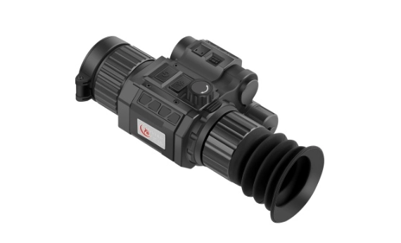
    Do not attempt unofficial firmware repair procedures unless the manufacturer provides them.

    Do Not Disassemble the Thermal Core or Housing

    A thermal scope is not normally a user-serviceable optical assembly.

    Opening the housing can affect:

    • environmental sealing;
    • detector alignment;
    • display alignment;
    • electrical connections;
    • calibration state.

    Internal repair should be performed only under the correct service procedure.

    This is especially important after water ingress, impact or internal fogging.

    Long-Term Storage Can Create Its Own Risks

    A thermal scope should normally be stored:

    • clean;
    • dry;
    • within its specified storage-temperature range;
    • protected from hard impact.

    Do not seal a wet device inside a closed case for long-term storage.

    For devices with removable batteries, some manufacturers recommend removing the battery during prolonged storage; the exact recommendation depends on the battery system. Pulsar, for example, instructs users of several thermal devices to store them in a dry, ventilated location and remove the battery for long storage.

    A Protective Case Helps, but It Does Not Eliminate Environmental Risk

    A padded case can protect against:

    • scratches;
    • transport impact;
    • dirt.

    But a case can also trap moisture if a wet device is placed inside and immediately sealed.

    After exposure to rain or condensation:

    dry the exterior appropriately before long-term enclosed storage.

    The case itself should also be dry and clean.

    How Long Can a Thermal Scope Last?

    There is no universal service-life figure for a thermal scope. Useful lifespan depends on the design and condition of the thermal core, electronics, display, seals, controls, battery system, mounting interface, and other components, as well as recoil history, environmental exposure, storage conditions, and maintenance. A warranty period is not the same as expected service life, and individual components can age at different rates.

    The practical way to support long service life is to avoid preventable damage: keep the device within its specified operating and storage limits, protect it from impacts and moisture, use approved batteries and charging methods, clean optical surfaces correctly, and follow the manufacturer’s inspection and service guidance. If image quality, controls, power behavior, sealing, or zero retention changes unexpectedly, diagnose the specific issue rather than assuming the entire thermal system has reached a fixed age limit.

    Common Thermal-Scope Damage Risks

    RiskWhat It Can AffectBetter Practice
    Direct intense energy sourceDetector/electronics depending on designFollow exact sun/laser warning
    Excessive heatBattery/electronics/materialsStay within model temperature limits
    Extreme coldBattery/runtime/performanceFollow model operating range
    Rapid temperature changeExternal condensationAllow controlled acclimation
    Water ingressElectronics/internal opticsRespect exact IP conditions
    Salt exposureSurfaces/contacts/coatingsFollow approved cleaning procedure
    Sand or gritOptical coatings/mechanismsRemove particles before wiping
    Hard impactHousing/mount/optics/electronicsInspect after significant impact
    Excess recoilMechanical/electronic systemUse only within verified rating
    Loose mountAlignment/zeroInspect mounting interface
    Excessive tighteningThreads/housing/mountFollow specified torque
    Wrong battery/chargerBattery/power electronicsUse approved power system
    Poor lens cleaningExternal optical coatingUse optical-safe method
    Wet storageCorrosion/moisture problemsDry before long-term storage
    Unauthorized disassemblySeals/alignment/calibrationUse proper service procedure

    What Is Not Automatically Evidence of Damage?

    Some changes can look alarming without proving permanent failure.

    Examples include:

    • shorter runtime in cold conditions;
    • temporary external condensation;
    • a different image appearance after weather changes;
    • reduced contrast in high humidity;
    • a zero change caused by a loose mount;
    • normal calibration events.

    Thermal-image performance depends strongly on environmental conditions.

    Do not confuse a difficult thermal scene with hardware damage.

    For more context, see how weather affects thermal imaging performance.

    When Should You Stop Using the Device and Have It Inspected?

    Stop treating the problem as routine maintenance when you observe:

    • persistent internal fogging;
    • visible housing crack;
    • battery swelling or leakage;
    • damaged charging connector;
    • loose internal component;
    • repeated unexpected shutdown;
    • abnormal image that persists after normal calibration;
    • significant mount or housing deformation;
    • evidence of water inside the enclosure.

    Do not continue trying random cleaning or reset procedures if the problem appears mechanical or electrical.

    The appropriate next step is the service procedure for the exact product.

    Current Yubeen Thermal Products Should Be Evaluated by Their Exact Specifications

    Yubeen’s current thermal range includes products designed for outdoor observation and field use.

    Yubeen thermal imaging rifle scope for long-range target observation
    A current Yubeen thermal imaging product. Environmental, shock, battery and operating limits vary by model and should be checked from the exact specification.

    The exact product documentation should determine:

    • operating temperature;
    • storage temperature;
    • IP rating;
    • shock specification;
    • battery type;
    • charging method;
    • lens-care instructions;
    • approved mounting method.

    Do not transfer a durability specification from one Yubeen model to another.

    Likewise, do not describe a model as:

    • waterproof beyond its documented IP condition;
    • saltwater-proof;
    • indestructible;
    • immune to recoil;
    • protected from direct solar exposure

    unless the exact documentation supports that claim.

    You can review the current Yubeen thermal imaging range for current model information.

    A Simple Thermal-Scope Care Checklist

    Before use:

    1. inspect the housing and lens;
    2. check battery condition;
    3. confirm covers are properly closed;
    4. inspect the mount.

    After wet, dusty, or salty use:

    1. remove loose contamination first;
    2. clean optics only with an approved method;
    3. dry the exterior appropriately;
    4. inspect ports and covers.

    For storage:

    1. keep the device dry and protected;
    2. follow the exact battery-storage guidance;
    3. remain within storage-temperature limits;
    4. avoid deliberate exposure to intense energy sources.

    That routine addresses most preventable risks without creating new ones through excessive maintenance.

    Thermal Scopes Are Durable Within Defined Limits

    Modern thermal devices can be engineered for difficult outdoor conditions.

    But durability is always defined by specific design and test limits.

    An IP rating has boundaries.

    A shock rating has test conditions.

    A battery has an approved operating range.

    An optical coating has an appropriate cleaning method.

    The best protection therefore comes from understanding the exact product rather than relying on labels such as:

    rugged, waterproof, all-weather, or recoil-proof.

    Those words are useful only when tied to verified technical specifications.

    FAQ

    Can Direct Sunlight Damage a Thermal Scope?

    Many thermal-device manufacturers explicitly warn against pointing the objective directly at the sun or other strong energy sources. The actual risk depends on the device design, so follow the exact product manual rather than assuming all detectors behave identically.

    Can I Use a Thermal Scope During the Day?

    Yes, thermal imaging can operate during daylight. Normal daytime observation is different from deliberately aiming the objective at the solar disk or another intense energy source.

    Can Cold Weather Permanently Damage a Thermal Scope?

    Not necessarily. Cold often reduces battery performance first. Permanent damage depends on whether the device is operated or stored outside its specified limits.

    Does IP67 Mean a Thermal Scope Cannot Be Damaged by Water?

    No. IP67 refers to defined ingress-testing conditions. It does not mean unlimited immersion, damaged seals, open ports or saltwater exposure are harmless.

    Can Recoil Damage a Thermal Scope?

    It can if the mechanical environment exceeds what the specific device was designed and qualified to withstand. Use the exact product’s recoil or shock specification rather than a generic rule.

    Can Alcohol Be Used on a Thermal Lens?

    There is no universal answer. Cleaning chemicals and lens coatings vary. Use only the cleaning materials approved for the exact device.

    Should I Clean a Thermal Objective After Every Use?

    Not necessarily. Remove contamination when needed, and remove loose abrasive particles before touching the optical surface.

    What Should I Do if My Thermal Scope Fogs Internally?

    Persistent moisture inside a sealed assembly should not be treated as ordinary external condensation. Do not open the housing; use the appropriate inspection or service procedure.

  • Can You Use a Thermal Imaging Scope in Daylight? What Changes During the Day

    Can You Use a Thermal Imaging Scope in Daylight? What Changes During the Day

    A thermal imaging scope in daylight can operate normally, but the thermal scene may look very different from the same location at night.

    A thermal imaging scope forms an image from infrared radiation reaching its detector rather than from visible light reflected by the scene. That means normal daylight does not prevent the thermal detector from operating.

    But daytime use is not simply “nighttime performance with the sun turned on.”

    Sunlight changes the temperatures of ground, vegetation, buildings, rocks, metal, and other surfaces. Those changes can increase or reduce the thermal contrast between a target and its background. Reflective surfaces can also create thermal patterns that are easy to misinterpret, while hot weather, humidity, and atmospheric conditions can affect practical image quality.

    The better question is therefore not only:

    “Can a thermal imaging scope work during the day?”

    but:

    “How does the daytime thermal environment change what the detector sees?”

    If you are new to thermal imaging itself, start with our guide to thermal imaging for beginners.

    Thermal Imaging Does Not Need Visible Light

    Visible-light cameras form images from light reflected by the scene.

    Traditional low-light and image-intensification systems also depend, directly or indirectly, on available light.

    Thermal imaging uses a different signal.

    Objects emit infrared radiation according to their temperature and surface properties. A thermal detector receives differences in that infrared energy and converts them into electrical signals that can be processed into an image.

    This is why a thermal imager can operate:

    • in daylight;
    • at dusk;
    • at night;
    • in complete darkness.

    Visible illumination is not the primary requirement for image formation. FLIR describes thermal imaging as capable of producing images in both darkness and bright daylight because the detector responds to infrared radiation rather than relying on visible scene illumination.

    For a deeper explanation of the detector itself, see our guide to thermal imaging FPA and microbolometers.

    Daylight Changes the Thermal Scene

    Although visible sunlight is not required by the detector, sunlight changes the temperatures of the surfaces being observed.

    During the day, solar energy can heat:

    • exposed soil;
    • rocks;
    • walls and roofs;
    • vehicles and machinery;
    • vegetation;
    • metal surfaces;
    • other outdoor materials.

    Different materials heat and cool at different rates.

    As a result, a scene viewed shortly after sunrise can have a very different thermal pattern from the same scene in mid-afternoon.

    This is the main reason daytime thermal imaging should not be described as identical to nighttime thermal imaging.

    The detector may operate in both cases.

    The scene has changed.

    Solar Loading Can Increase or Reduce Thermal Contrast

    Thermal contrast is the difference between the infrared signal from a target and the surrounding background.

    Strong thermal contrast makes an object easier to distinguish.

    Weak thermal contrast makes the target blend into the scene.

    Sunlight can produce either result.

    For example, solar heating may make one surface much warmer than its surroundings, increasing apparent contrast.

    But prolonged heating can also bring several materials toward similar apparent temperatures, reducing contrast between them.

    FLIR’s infrared-imaging guidance notes that outdoor solar loading can heat the lens, camera, and observed surfaces, changing the radiation received by the detector compared with controlled conditions.

    This means:

    brighter daylight does not automatically mean better or worse thermal imagery.

    What matters is how the thermal scene changes.

    Thermal Crossover Can Make a Scene Harder to Interpret

    The term thermal crossover is often used informally for periods when a target and its background approach similar apparent temperatures.

    This can occur during environmental transitions.

    For example, one material may heat faster after sunrise, while another retains heat longer after sunset.

    At some point their thermal signals may become relatively similar.

    When that happens, visible thermal contrast can decrease even though the detector is functioning normally.

    The exact timing depends on:

    • material;
    • surface condition;
    • solar exposure;
    • shade;
    • wind;
    • ambient temperature;
    • moisture;
    • target activity.

    There is no universal “worst time of day.”

    Thermal crossover depends on the actual scene.

    Conceptual diagram showing target-to-background thermal contrast changing with environmental conditions

    A Hot Afternoon Does Not Automatically Make Thermal Imaging Useless

    High ambient temperature does not switch off a thermal detector.

    However, hot conditions can reduce target-to-background contrast when many surfaces become warm.

    Consider a warm target against cool ground.

    The temperature separation may be strong.

    Now imagine the ground, rocks, and vegetation heating through the afternoon.

    As the background becomes warmer, the apparent difference can decrease.

    A sensitive detector may still preserve small differences, but the available thermal contrast has changed.

    This is where NETD becomes relevant.

    For more on sensitivity in low-contrast scenes, see NETD in thermal imaging.

    NETD Can Help When Daytime Contrast Is Weak

    NETD describes thermal sensitivity relative to system noise under stated measurement conditions.

    A lower NETD generally means smaller thermal differences can be distinguished relative to noise when comparison conditions are equivalent.

    That can be useful during low-contrast daytime conditions.

    But NETD does not create a temperature difference that does not exist.

    It also does not replace:

    • detector resolution;
    • optics;
    • focus;
    • field of view;
    • atmospheric transmission;
    • image processing.

    A low NETD value therefore should not be interpreted as a guarantee that every hot-afternoon scene will remain highly detailed.

    Detector Resolution Still Controls Spatial Sampling

    Daylight does not change the native number of detector pixels.

    A 384 × 288 detector remains 384 × 288.

    A 640 × 512 detector remains 640 × 512.

    Higher native detector resolution can provide more spatial samples when optics and field of view are comparable.

    But resolution cannot compensate completely for weak thermal contrast.

    A high-resolution detector still needs usable infrared information from the scene.

    This is why resolution and NETD solve different problems:

    • resolution → spatial information;
    • NETD → thermal sensitivity relative to noise.

    Reflective Surfaces Can Be Misleading

    Not every surface seen by a thermal detector behaves like an ideal emitter.

    A useful concept here is emissivity.

    High-emissivity surfaces emit infrared radiation efficiently.

    Low-emissivity surfaces—especially polished metals—can reflect a substantial amount of infrared radiation from their surroundings.

    FLIR notes that highly polished metals may behave almost like infrared mirrors, so the thermal camera can see reflected radiation from surrounding objects rather than a simple representation of the surface’s own temperature.

    This becomes particularly relevant outdoors, where sunlight and other warm objects can influence the apparent thermal pattern.

    Therefore, a bright or dark area on a shiny surface should not automatically be interpreted as the actual temperature of that surface.

    For a non-radiometric thermal scope, the practical lesson is simpler:

    reflective surfaces can create thermal appearances that require careful interpretation.

    Visible Color Does Not Tell You Thermal Emissivity

    A surface that looks dark in visible light is not necessarily a strong infrared emitter.

    Likewise, a shiny visible surface may behave very differently in the LWIR band.

    Thermal appearance depends on:

    • material;
    • surface finish;
    • emissivity;
    • reflection;
    • viewing angle;
    • surrounding infrared sources.

    That is why daytime thermal interpretation requires more than assuming:

    hotter-looking = physically hotter.

    This is especially important around polished metal, glass, water, and other reflective or partially reflective surfaces.

    Direct Sun Exposure Is a Separate Question

    Using a thermal imaging device during daylight is not the same as intentionally pointing it directly at the sun.

    Direct solar exposure creates a much more concentrated input than viewing a normal sunlit landscape.

    Different detector and optical systems may respond differently.

    For example, Teledyne FLIR states that it does not recommend intentionally viewing the sun with Boson, Tau2, or Quark2 cameras. For those specific cores, FLIR reports that solar viewing may produce temporary image artifacts and require recovery or flat-field correction.

    That information should not be generalized into a claim about every thermal product.

    The appropriate rule is:

    follow the direct-sun guidance for the exact device.

    Unless the manufacturer explicitly states otherwise, avoid prolonged intentional viewing of the sun.

    Daylight and Direct Sun Should Not Be Confused

    These two statements can both be true:

    A thermal imaging scope can normally be used during daylight.

    and:

    Intentionally pointing the system directly at the sun may be discouraged.

    There is no contradiction.

    Normal outdoor daylight means observing ordinary scenes illuminated and heated by the sun.

    Direct solar viewing means placing the solar disk itself within the optical field.

    Those are very different exposure conditions.

    Weather Still Matters During the Day

    Daylight does not eliminate atmospheric effects.

    Humidity, fog, rain, snow, and atmospheric path length can still reduce the infrared information reaching the detector.

    In addition, weather changes surface temperatures and therefore target-to-background contrast.

    For example:

    • rain can cool surfaces;
    • wet materials can change thermal behavior;
    • cloud cover can reduce solar heating;
    • wind can change surface temperature;
    • humidity can affect long-path transmission.

    For the complete environmental discussion, see how weather affects thermal imaging.

    Shadows Can Be Thermally Visible

    A visible-light shadow is created when direct illumination is blocked.

    Thermal scenes can show a related but different effect.

    A surface exposed to sunlight may heat more than an adjacent shaded surface.

    That temperature difference can remain visible thermally even after the visible lighting pattern changes.

    As a result, a thermal image may reveal:

    • warm sun-exposed surfaces;
    • cooler shaded regions;
    • retained heat after the light source changes.

    These are real thermal patterns, but they can complicate interpretation if they are mistaken for target-specific heat signatures.

    Daytime Image Quality Can Change Over Minutes or Hours

    A thermal scene is dynamic.

    Sunlight intensity changes.

    Clouds move.

    Surfaces heat.

    Shade moves.

    Wind changes convective cooling.

    Moisture evaporates.

    Because these processes happen at different rates, the thermal image of the same location can change significantly during the day.

    This means a product comparison made at 8:00 AM should not automatically be treated as equivalent to one made at 3:00 PM.

    When comparing thermal devices, use similar environmental and viewing conditions whenever possible.

    Automatic Gain Control Changes the Presentation

    Thermal devices commonly use image-processing functions that adjust the displayed contrast according to the current scene.

    Automatic gain control can redistribute display levels so useful differences remain visible.

    This can make the image appear dramatically different as the scene changes.

    That does not mean the detector’s physical resolution or NETD has changed.

    It means the available detector data are being presented differently.

    Likewise, palette selection can influence how easily a user notices certain differences without changing the underlying thermal measurements.

    NUC / FFC Is Not a Day-or-Night Mode

    Many uncooled thermal systems perform non-uniformity correction, often called NUC or FFC.

    This helps compensate for differences between detector elements and changes in detector behavior.

    It is not a switch between daytime and nighttime operation.

    Changing environmental temperature or device temperature can increase the need for calibration behavior in some systems, but the exact process is product-specific.
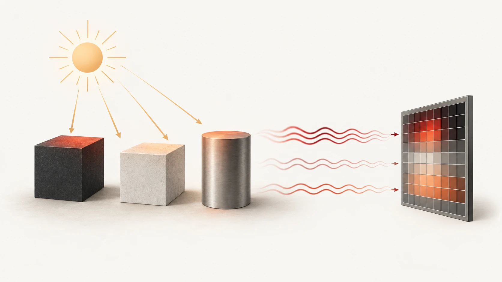
    FLIR describes NUC as a correction for detector non-uniformity rather than an illumination mode.

    Use the exact manufacturer’s procedure for the device.

    Digital Zoom Does Not Become More Powerful in Daylight

    Digital zoom enlarges thermal information already captured by the detector.

    It does not add native detector pixels.

    Daylight does not change this rule.

    A strong daytime thermal contrast may make an enlarged target easier to interpret.

    Weak contrast may make enlargement less useful.

    But maximum digital-zoom specification should not be confused with native spatial detail.

    For the relationship between detector data and computational enhancement, see our guide to AI processing in thermal scopes.

    Daytime DRI Still Depends on the Complete System

    Detection, recognition, and identification are different information tasks.

    Daytime thermal contrast can change the distance at which each task remains practical.

    A warm target against a thermally similar background may become harder to distinguish even in perfect visible daylight.

    Conversely, strong target-to-background contrast can make detection easier.

    Practical DRI still depends on:

    • target size;
    • detector resolution;
    • pixel pitch;
    • focal length;
    • FOV;
    • thermal contrast;
    • atmosphere;
    • NETD;
    • processing.

    For the full discussion, see thermal detection, recognition, and identification.

    Can a Thermal Imaging Scope Replace a Regular Optical Scope in Daylight?

    Not completely. A thermal imaging scope and a conventional optical scope provide different kinds of information. Thermal imaging emphasizes differences in emitted infrared energy, which can make heat signatures easier to detect against some backgrounds. A conventional optical scope uses visible light and can provide color, texture, surface detail, and other visual information that thermal imaging does not reproduce.

    For daytime use, thermal imaging is therefore better treated as complementary rather than as a universal replacement for conventional optics. Thermal can be useful for detection and scanning, while visual identification may still benefit from an optical scope or binoculars when conditions allow. The practical choice depends on target size, thermal contrast, distance, field of view, detector detail, optics, and how much visual confirmation is required.

    What Specifications Matter for Daytime Thermal Use?

    The same core specifications still matter during the day:

    FactorWhy it matters
    Detector resolutionNative spatial sampling
    NETDSensitivity to small thermal differences
    Pixel pitchDetector geometry and IFOV with the lens
    Focal length / FOVScene coverage and angular sampling
    Lens qualityInfrared transmission and focus
    Image processingPresentation of available thermal data
    DisplayUser viewing and interface presentation
    Operating temperatureSupported environmental range for the exact product
    Battery systemPractical operating time
    Environmental protectionProduct-specific exposure limits

    Daytime operation does not create a separate set of thermal physics.

    It changes the scene in which the system operates.

    A Real Product Still Needs Exact Daytime Specifications

    A current thermal product can be used here as a real brand example without claiming that one model represents all daylight conditions.

    Current Yubeen thermal imaging product shown as a daytime-use example

    For the exact product, verify:

    • native detector specification;
    • NETD;
    • optics;
    • FOV;
    • operating-temperature range;
    • direct-sun guidance;
    • environmental protection;
    • battery/runtime conditions;
    • calibration procedure.

    Do not infer these specifications from another product in the same family.

    A real product image should connect the technical article to the Yubeen range—not serve as proof of an unsupported “all-day” performance claim.

    How to Evaluate a Thermal Scope During Daylight

    A practical evaluation can be done in this order:

    1. Choose a realistic scene.
      Include both warm and cool materials rather than one artificially high-contrast target.
    2. Observe at more than one time of day.
      Morning and afternoon thermal patterns can differ significantly.
    3. Check target-to-background contrast.
      Determine whether objects remain distinguishable as the background warms.
    4. Look at reflective surfaces carefully.
      Do not assume every apparent thermal pattern represents surface temperature.
    5. Compare the same FOV.
      Different fields of view can make one system appear more detailed than another.
    6. Use comparable focus.
      Poor focus can overwhelm differences between detectors.
    7. Check image processing separately.
      Strong sharpening or gain adjustment can change appearance without changing native detector capability.
    8. Avoid intentional direct solar viewing unless explicitly permitted.
    9. Check current operating-temperature limits for the exact device.
    10. Compare products under similar environmental conditions.
      Uncontrolled screenshots taken at different times are weak evidence.

    What Daylight Thermal Imaging Can—and Cannot—Tell You

    Thermal imaging can:

    • operate without visible illumination;
    • remain usable in bright daylight;
    • reveal differences in infrared radiation that visible imagery may not show;
    • reveal thermal effects from sunlight, shade, and surface heating;
    • support observation across both day and night conditions.

    Thermal imaging cannot:

    • guarantee the same contrast at every time of day;
    • make all surfaces easy to interpret;
    • eliminate reflection from low-emissivity surfaces;
    • turn digital zoom into additional detector resolution;
    • guarantee identical DRI range in daytime and nighttime;
    • justify prolonged direct solar viewing without product-specific guidance.

    The key point is simple:

    daylight does not prevent thermal imaging, but it changes the thermal environment being imaged.

    FAQ

    Will sunlight damageCan a Thermal Imaging Scope Work in Bright Daylight? my thermal imaging scope?

    Yes. Thermal imaging does not depend on visible-light illumination, so normal daylight does not prevent image formation. However, solar heating can change target-to-background thermal contrast and therefore change the appearance of the scene.

    Is Daytime Thermal Imaging as Good as Nighttime Thermal Imaging?

    Not necessarily better or worse. Performance depends on the thermal contrast of the actual scene. Some targets may stand out more strongly at night, while other daytime conditions can produce useful contrast.

    Can Direct Sunlight Damage a Thermal Imaging Scope?

    The answer is product-specific. Normal daylight use and intentionally pointing the optic directly at the sun are different conditions. Some thermal-core manufacturers explicitly discourage intentional solar viewing, so follow the guidance for the exact product.
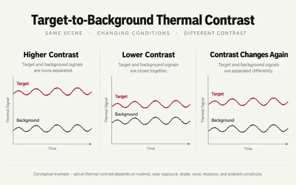
    Why Does Thermal Contrast Sometimes Get Worse on Hot Afternoons?

    Solar heating can bring the temperatures of different surfaces closer together. When target and background signals become similar, thermal contrast decreases even though the detector continues operating normally.

    Why Can Shiny Metal Look Strange in a Thermal Image?

    Low-emissivity surfaces such as polished metal can reflect infrared radiation from their surroundings. The displayed pattern may therefore include reflected thermal energy rather than representing only the surface’s own temperature.

    Does Daylight Improve Thermal Detection Range?

    Not automatically. Daytime solar heating can increase or decrease target contrast. Practical range still depends on detector resolution, optics, NETD, field of view, target size, atmosphere, and processing.